Proceedings Home | W2W Home 
*Do not make slides downloadable
Purpose
For centuries, farmers have disposed of manure by simply spreading it on the land. It is a natural fertilizer. Today, that practice is no longer considered the best solution. Field spreading is now understood to contribute to a growing global problem of the pollution of water, soil, and air. Consequently, U.S. dairy farmers face increased fiscal and operational pressure from the progression of ever tightening environmental regulations. Conventional handling of manure also imposes a number of operational challenges (limitations for storage, land application and irrigation, settlement in lagoons, high manure hauling costs, etc.) and typically requires a relatively large land base to allow adequate nutrient management.
In Indiana, a dairy that was daily producing thousands of tons of livestock waste was investigating how technology could capture the valuable nutrients remaining in their cow manure after it had gone through the farm’s anaerobic digestion process. Their goal was to convert the manure/digestate into a nutrient rich cake that could be easier managed and made into fertilizer, and the liquid clean enough to be used unrestricted for land application.
The farm’s key operational deliverables were 1) to reduce the manure’s handling and transportation costs, 2) allow for precision applications of the processed manure as carbon-based fertilizer and 3) allow for re-use of nutrient reduced liquid for field irrigation.
What did we do?
The dairy farm chose to implement a nutrient recovery technology from Trident Processes LLC. The technology separates the manure/digestate into three fractions: 1) cellulosic fiber, 2) a concentrated cake of nutrient enriched solids, and 3) water with about 1% remaining solids.
Trident’s turn-key system, consisting of different mechanical and chemical components, processes the manure and diverts each separated fraction into their separate spaces. Sensors and programmable controls (PLC) allow for smooth operation, requiring minimal operator attendance. The entire system can be monitored, controlled and diagnosed remotely.
The manure is fed into the system following the digestion process. The initial step is the extraction of the large fiber, which is done via a rotary screen conditioner. The wetted material separates, with the effluent water and fine solids sifting down through the screen while the larger fiber is retained. This step is critical as it ensures the fine particles, which contain the nutrients, are sent down stream for further treatment.
FIBER: The extracted fiber is sent to a screw press for further dewatering. This renders it as a 30% dry cellulosic fiber biomass that is ideal for recycling as cow bedding or other biomass use. Any liquid squeezed from the fiber is diverted to join the fine solids stream.
SOLIDS: The effluent water and solids are sent to a dissolved air flotation (DAF) tank. Polymerization ensures effective flocculation of the feedstock, resulting in a concentration of the nutrient rich particles that float to the surface. The sludge formed on the surface is skimmed off the top and gravity fed into a multi-disc press for second-stage dewatering. The press gently dewaters and thickens the recovered solid/nutrient sludge into a 25% solids, nutrient rich cake.
WATER: The final effluent water, now nutrient reduced, contains less than 1.2% solids and is sent to the lagoon for storage. The water is then reused for irrigation through efficient pivot systems or as operational water on the farm.
What have we learned?
By implementing Trident’s Nutrient Recovery System, the farms’ objectives have been met and/or exceeded. After running for nearly two years the system is producing the following statistics:
• Fully automated operation requiring about 1 hr/shift for operator attendance (visual checks)
• 98% system uptime
• Polymer costs: $0.06 – $0.08/day/cow
• Reduction of handling and irrigation costs: $ 0.01/gal (conventional) vs $0.003/gal (center pivot)
• $250,000/yr electrical power savings with MD Press vs. centrifuge
• 73,000+ ton/yr nutrient cake produced
• 81% P, 70% organic N (54% TKN), and 20% K is the average nutrient capture rate
• 1% (max.) solids in the effluent water sent to lagoons
• 99% Suspended solids captured
Future Plans
Dairy farm: A fertilizer plant will go live in the near future, allowing the farm to sell their concentrated nutrients to the plant as feedstock for custom fertilizer production.
Technology provider: 2nd Phase effluent treatment to capture and retain the solid and nutrient fraction of the existing process, allowing to meet stream discharge standards and comply with BOD / COD levels. Bench scale testing is completed. Farm scale pilot testing is scheduled to run from March 2017-December 2017.
Corresponding author, title, and affiliation
Richard Shatto (Senior Partner at Point Nexus Consulting), Frank Engel (Director Marketing at KPD Consulting Ltd.)
Corresponding author email
Additional information
https://youtu.be/PvaTGmyws-w (Carl Ramsey’s presentation at Indiana Dairy Forum)
http://www.progressivedairy.com/topics/manure/prairie-s-edge-dairy-on-pa… (Progressive Dairyman article)
http://tridentprocesses.com/documents/case-study-trident-nutrient-recove… (Newtrient case study)
https://are.wisc.edu/manure-processing/ (manure management project with University of Wisconsin)
http://www.foodqualityandsafety.com/article/nutrient-recovery-improves-s… (Nutrient Recovery Improves Sustainability article in Food Quality & Safety Magazine)
Acknowledgements
Carl Ramsey, Environmental Manager at Prairie’s Edge Dairy Farm
Soil Net LLC, Dr. Aicardo Roa (strategic partner for chemical separation process)
Leap Tech, R.C. Ludke (strategic partner for automation)
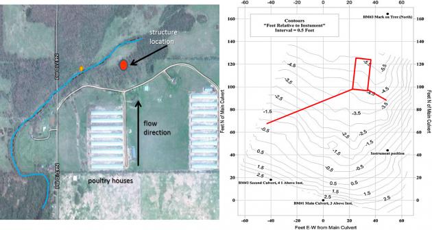 gpm flow rate. Several hypothetical designs were made based on the available P sorbing materials (PSMs), such as drinking water treatment residuals, acid mine residuals, and gypsum. We chose to use a treated steel slag material as the PSM in the structure; this required about 35 tons of material.
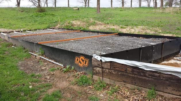 We constructed a P removal structure on a poultry farm in Eastern OK; this is a BMP that can remove dissolved P loading in the short term until soil legacy P concentrations decrease below levels of environmental concern. A P removal structure contains P sorbing materials (PSMs) and are placed in a location to intercept runoff or subsurface drainage with high dissolved P concentrations. As high P water flows through the PSMs, dissolved P is sorbed onto the materials by several potential mechanisms, allowing low P water to exit the structure. While they vary in form, P removal structures contain three main elements: 1) use of a filter material that has a high affinity for P, 2) containment of the material, and 3) the ability to remove that material and replace it after it becomes saturated with P and is no longer effective.
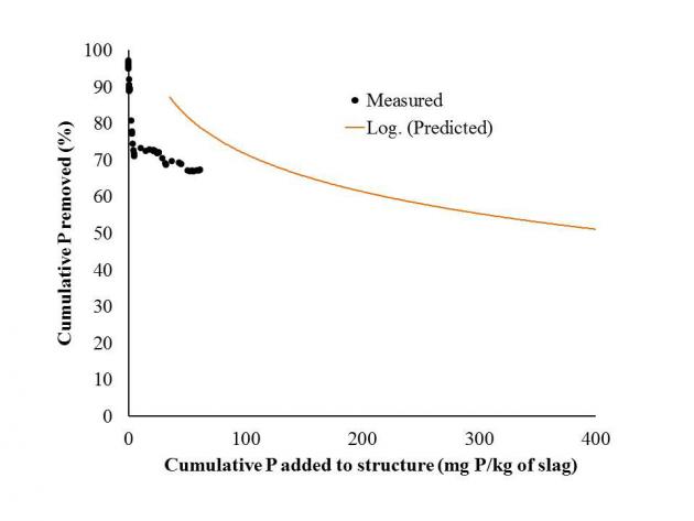 The P removal structure has removed approximately 67% of all dissolved P that has flowed into it over a 16-month time period. In addition, it has handled all flow volume from every event, including a runoff event that resulted in 600 gpm. That single event delivered 2/3 lb of dissolved P, in which the structure removed 66%. While the structure is removing P as predicted based on P loading, the structure has greatly outlasted the goal of removing 45% of cumulative dissolved P in one year. This is due to the below average rainfall received over the last two years.
 We will continue to monitor the structure. In addition, we are cooperating with several people throughout the US in helping to design P removal structures. We are also releasing design software for licensing in an attempt to promote commercialization of this BMP through private industry. A NRCS standard is currently underway and the goal is for this BMP to become cost-shared. Last, we are continuing to investigate the economics of P removal structure over a large scale area.