Manure Management Technology Selection Guidance

Proceedings Home W2W Home w2w17 logo

Purpose

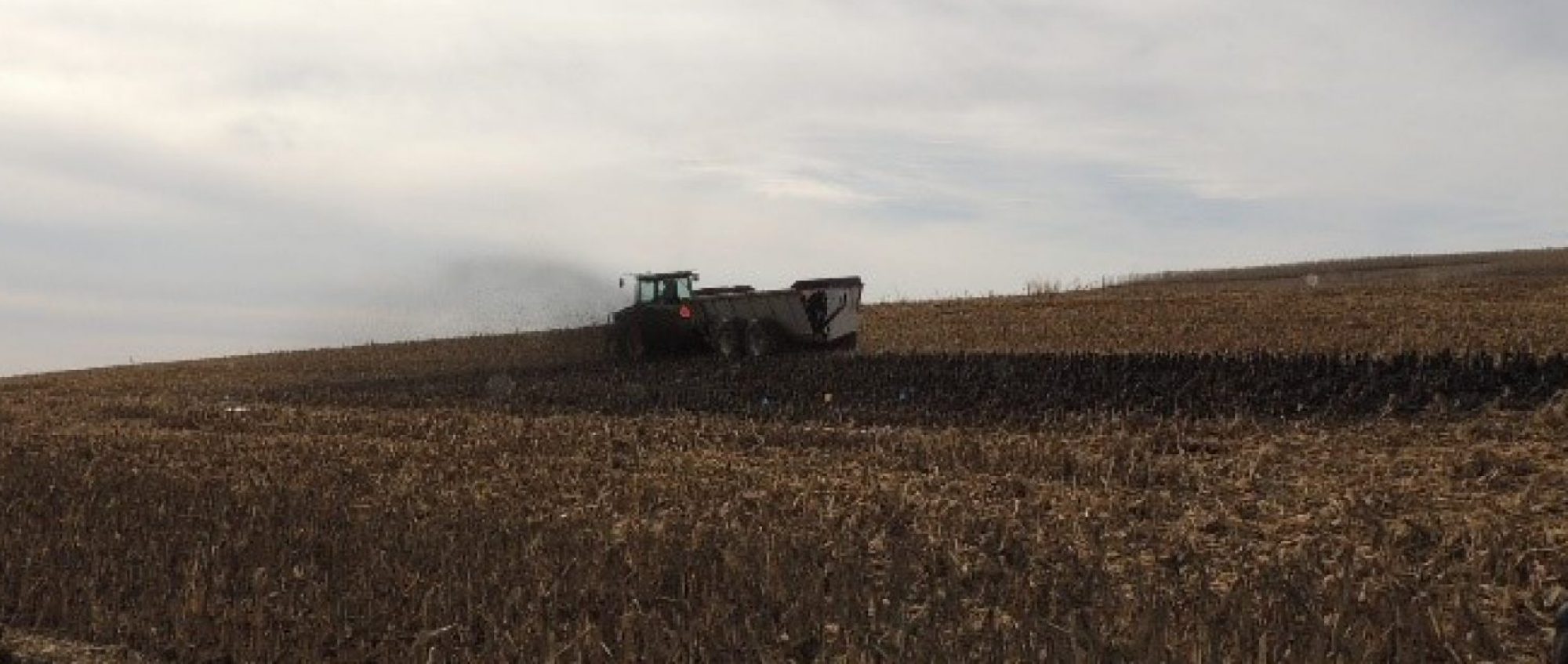
Manure is an inevitable by-product of livestock production. Traditionally, manure has been land applied for the nutrient value in crop production and improved soil quality.With livestock operations getting larger and, in many cases, concentrating in certain areas of the country, it is becoming more difficult to balance manure applications to plant uptake needs. In many places, this imbalance has led to over-application of nutrients with increased potential for surface water, ground water and air quality impairments. No two livestock operations are identical and manure management technologies are generally quite expensive, so it is important to choose the right technology for a specific livestock operation. Information is provided to assist planners and landowners in selecting the right technology to appropriately address the associated manure management concerns.

What did we do?

As with developing a good conservation plan, knowledge of manure management technologies can help landowners and operators best address resource concerns related to animal manure management. There are so many things to consider when looking at selecting various manure treatment technologies to make sure that it will function properly within an operation. From a technology standpoint, users must understand the different applications related to physical, chemical, and biological unit processes which can greatly assist an operator in choosing the most appropriate technology. By having a good understanding of the advantages and disadvantages of these technologies, better decisions can be made to address the manure-related resource concerns and help landowners:

• Install conservation practices to address and avoid soil erosion, water and air quality issues.

• In the use of innovative technologies that will reduce excess manure volume and nutrients and provide value-added products.

• In the use of cover crops and rotational cropping systems to uptake nutrients at a rate more closely related to those from applied animal manures.

• In the use of local manure to provide nutrients for locally grown crops and, when possible, discourage the importation of externally produced feed products.

• When excess manure can no longer be applied to local land, to select options that make feasible the transport of manure nutrients to regions where nutrients are needed.

• Better understand the benefits and limitations of the various manure management technologies.

Picture of holding tank

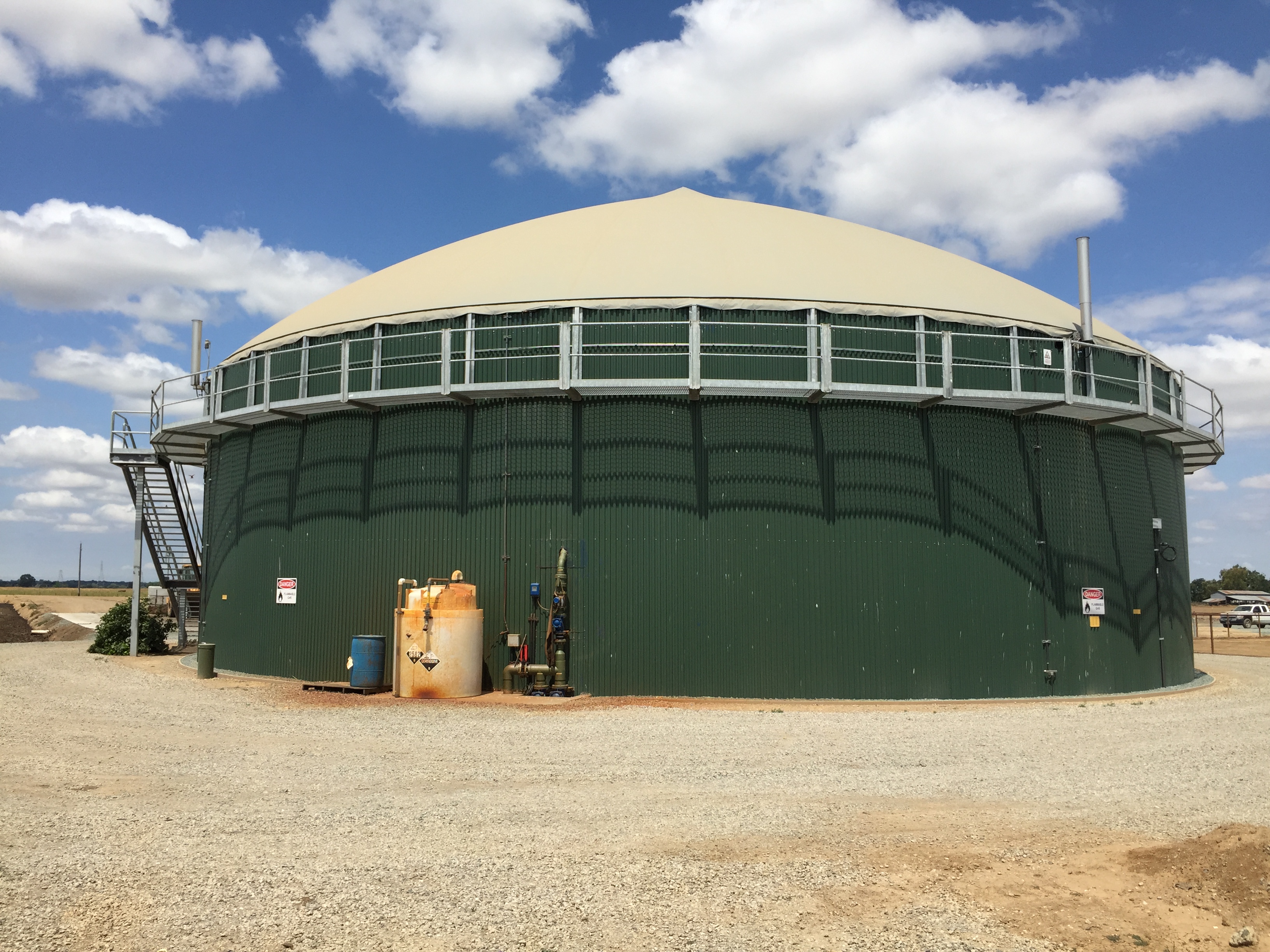
Complete-Mix Anaerobic Digester – option to reduce odors and pathogens; potential energy production

Picture of mechanical equipment

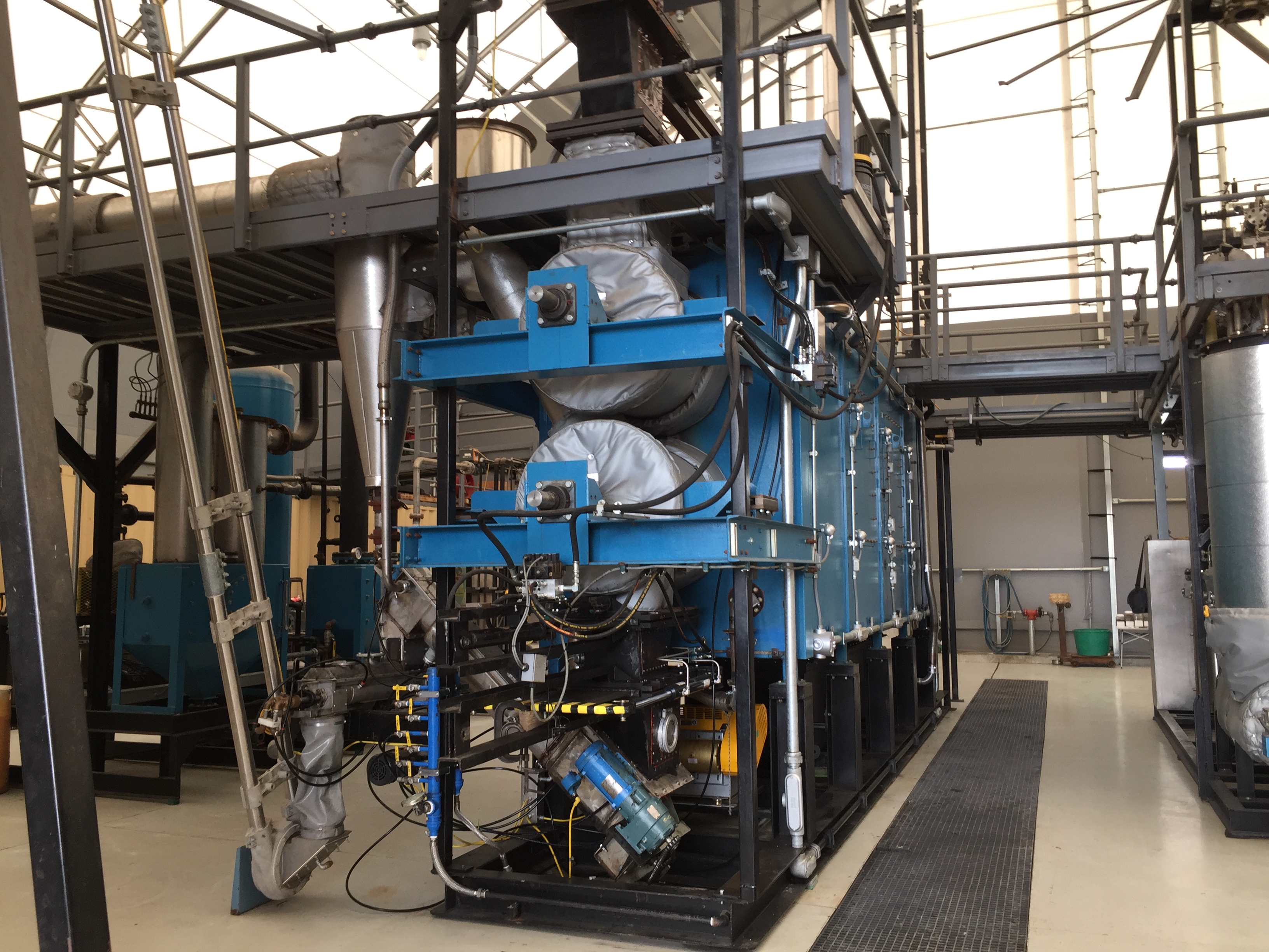
Gasification (pyrolysis) system – for reduced odors; pathogen destruction; volume reduction; potential energy production.

Picture of field

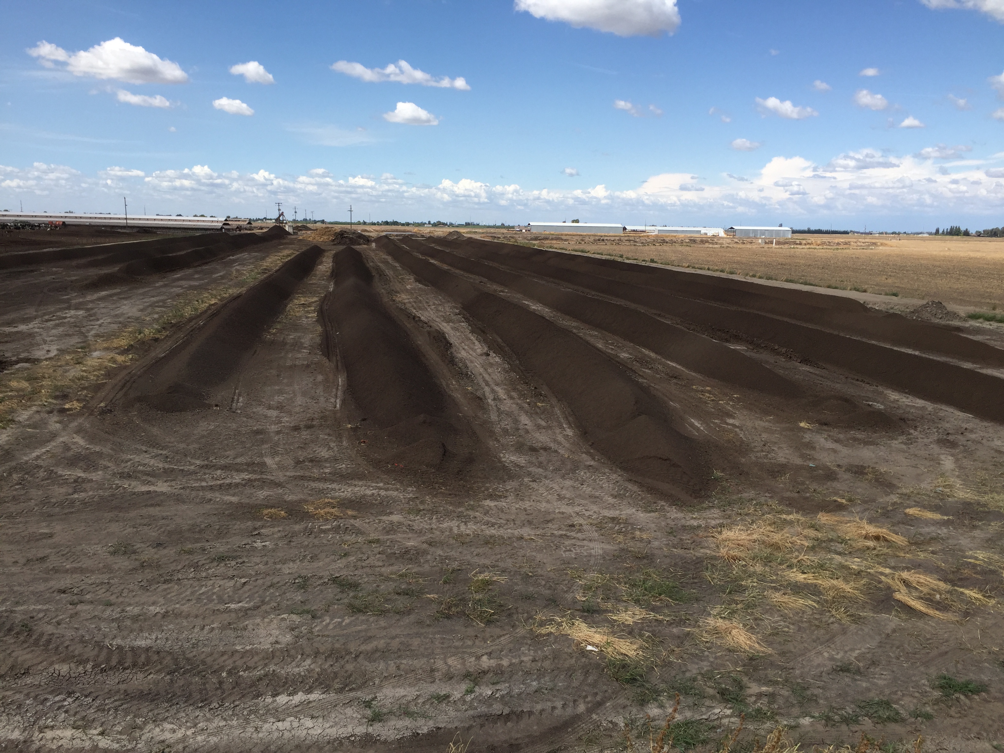
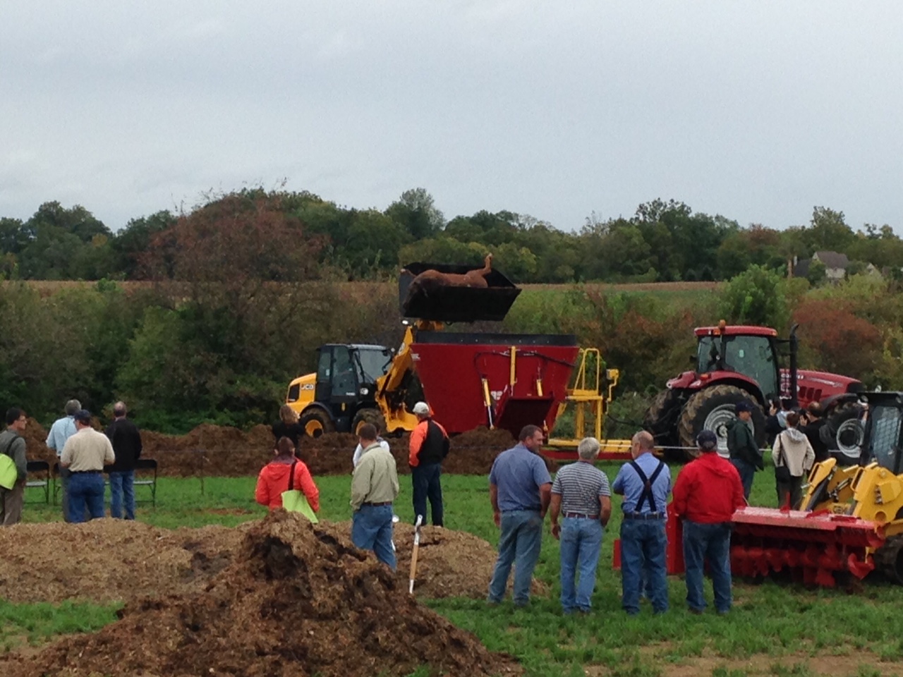
Windrow composting – reduce pathogens; volume reduction

Picture of Flottweg separation technology

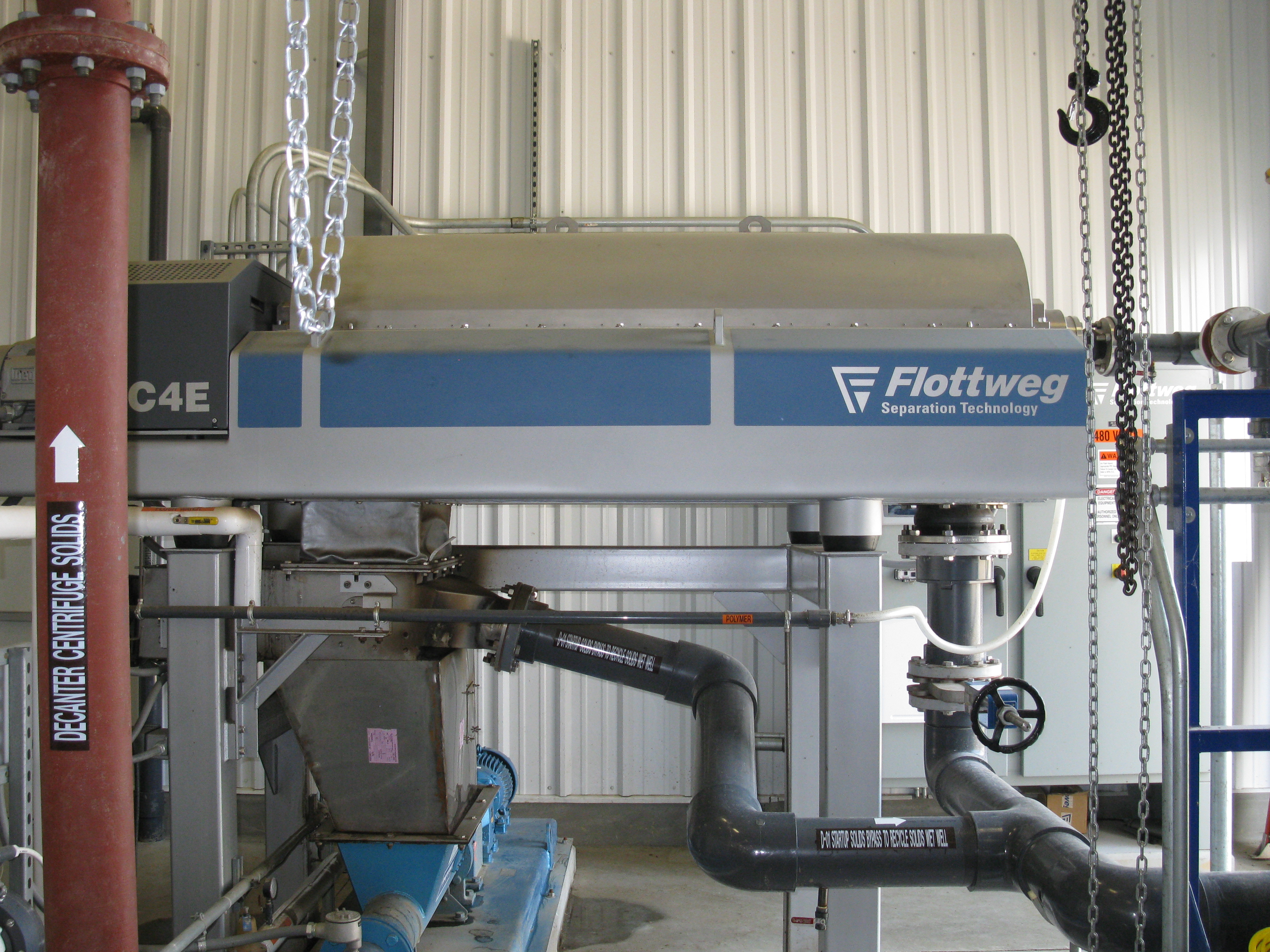
Centrifuge separation system – multiple material streams; potential nutrient
partitioning.

What have we learned?

• There are several options for addressing manure distribution and application management issues. There is no silver bullet.

• Each livestock operation will need to be evaluated separately, because there is no single alternative which will address all manure management issues and concerns.

• Option selections are dependent on a number of factors such as: landowner objectives, manure consistency, land availability, nutrient loads, and available markets.

• Several alternatives may need to be combined to meet the desired outcome.

• Soil erosion, water and air quality concerns also need to be addressed when dealing with manure management issues.

• Most options require significant financial investment.

Future Plans

Work with technology providers and others to further evaluate technologies and update information as necessary. Incorporate findings into NRCS handbooks and fact sheets for use by staff and landowners in selecting the best technology for particular livestock operations.

Corresponding author, title, and affiliation

Jeffrey P. Porter, P.E.; National Animal Manure and Nutrient Management Team Leader USDA-Natural Resources Conservation Service

Corresponding author email

jeffrey.porter@gnb.usda.gov

Other authors

Darren Hickman, P.E., National Geospatial Center of Excellence Director USDA-Natural Resources Conservation Service; John Davis, National Nutrient Management Specialist USDA-Natural Resources Conservation Service, retired

Additional information

References

USDA-NRCS Handbooks – Title 210, Part 651 – Agricultural Waste Management Field Handbook

USDA-NRCS Handbooks – Title 210, Part 637 – Environmental Engineering, Chapter 4 – Solid-liquid Separation Alternatives for Manure Handling and Treatment (soon to be published)

Webinars

Evaluation of Manure Management Systems – http://www.conservationwebinars.net/webinars/evaluation-of-manure-management-systems/?searchterm=animal waste

Use of Solid-Liquid Separation Alternatives for Manure Handling and Treatment – http://www.conservationwebinars.net/webinars/use-of-solid-liquid-separation-alternatives-for-manure-handling-and-treatment/?searchterm=animal waste

The authors are solely responsible for the content of these proceedings. The technical information does not necessarily reflect the official position of the sponsoring agencies or institutions represented by planning committee members, and inclusion and distribution herein does not constitute an endorsement of views expressed by the same. Printed materials included herein are not refereed publications. Citations should appear as follows. EXAMPLE: Authors. 2017. Title of presentation. Waste to Worth: Spreading Science and Solutions. Cary, NC. April 18-21, 2017. URL of this page. Accessed on: today’s date.

Organizing demonstrations and tours for Government officials and Extension on Animal Mortality Management

Proceedings Home W2W Home w2w17 logo

Purpose

Provide some discussion on putting together Tour and Demonstration educational events. To Provide real life demonstrations and educational opportunities dealing with Mortality management.

What did we do?

The agent participated on a multi-state and multi country steering committee to organize and host an international symposium on Animal Mortality and Disposal Management. This was the 5th symposium and had 179 registered attendees from 11 different countries: Australia, Canada, China, Georgia, Korea, New Zealand, Nigeria, the UK, the US, Tunisia, and Vietnam.

The agent served as the host state coordinator (Penn), the 3 bus tour coordinator and the demonstration’s chairperson. Demonstrations included high density foaming, compost pile building and turning, environmental grinder processors, Clean Harbor Industries,  truck wash stations, and proper euthanasia with cap and bolt guns. The agent will list the success and challenges of these types of demonstrations and educational events. Results are from the 5th International Symposium on Managing Animal Mortality, Products, and By-products, and Associated Health Risk: Connecting Research, Regulations and Response at the Southeast Agricultural Research and Extension Center on Wednesday, September 30, 2015.

Moving horse for mortality composting
Examples of demonstrations during the field day

What have we learned?

Excellent industry tours and Farm tours and Demonstrations are an excellent learning opportunity. All Parties including Extension, Farmers, Industry and government personnel can benefit from hands on education.  Those in attendance gained skills and knowledge to be able to host their own training sessions and to be better prepared to handle animal mortality outbreaks and events in their own state.  They gained a first hand experience on pile building and related technologies for this type of event.

Demo with tractor covering mortality composting pile
Turning of a 60 day compost pile

Future Plans

The International Committee on Animal Mortality and Waste Products is a collection of University researchers and educators, State Department of Agriculture, Federal Homeland Security and Environmental Protection Agency personnel. The committee plans to meet for future International Symposiums as needed.

http://animalmortmgmt.org/symposium/contributors/

Corresponding author, title, and affiliation

J Craig Williams, County Agent, Penn State Extension

Corresponding author email

jcw17@psu.edu

Additional information

Conference website

http://animalmortmgmt.org/

The authors are solely responsible for the content of these proceedings. The technical information does not necessarily reflect the official position of the sponsoring agencies or institutions represented by planning committee members, and inclusion and distribution herein does not constitute an endorsement of views expressed by the same. Printed materials included herein are not refereed publications. Citations should appear as follows. EXAMPLE: Authors. 2017. Title of presentation. Waste to Worth: Spreading Science and Solutions. Cary, NC. April 18-21, 2017. URL of this page. Accessed on: today’s date.

Developing a Comprehensive Nutrient Management Plan (CNMP)

Proceedings Home W2W Home w2w17 logo

Purpose

Livestock producers are presented with a number of challenges and opportunities. Developing a quality Comprehensive Nutrient Management Plan (CNMP) can effectively help landowners address natural resource concerns related to soil erosion, water quality, and air quality from manure management. As livestock operations continue to expand and concentrate in certain parts of the country, utilizing a CNMP becomes even more important. Following the NRCS 9-step planning process is critical in developing a good plan. Effective communication is a key element between all parties involved in the planning process. A CNMP documents the decisions made by the landowner for the farmstead area, crop and pasture area, and nutrient management. Information will cover the elements essential for developing a quality CNMP.

What did we do?

Since the CNMP documents the records of decisions by the landowner, it has to be organized in such a fashion that it is understandable to and usable by the landowner. The CNMP is the landowner’s plan. Therefore, the role of the planner is to help landowners do the things that will most benefit them and the resources in the long run. This will take both time and effort. To provide consistency with other conservation planning efforts within NRCS, CNMPs following the same process outlined in the National Planning Procedures Handbook. There are several items that are essential for a quality CNMP to be developed:

• Have a good understanding of potential resource concerns especially soil erosion, water quality and air quality.

• Make the appropriate number of site visits. Trying to do this from the office will likely lead to a poor quality CNMP that may not be implemented.

• Address resource concerns for the Farmstead and Crop and Pasture areas.

• Ensure that all nutrient sources are addressed.

• Follow the 9 steps of planning.

• Decisions are agreed upon by the landowner. The CNMP reflects the landowner’s record of decisions.

• Follow-up to address any questions or concerns.

• Update as necessary. A CNMP is not a static document.

Field

Land application of animal manure without proper land treatment practices

Muddy field with standing water

Proper animal manure storage required to address water quality issues

Picture of lined water bed

Evaluation of storage area to adequately address surface and subsurface
water quality issues

Picture of tractor and tanker spreader

Land application and nutrient management are critical elements for a
properly prepared CNMP

What have we learned?

The quality of CNMPs varies greatly across the country. Some were becoming so large that landowners were having difficulty finding the activities that needed to be completed. The revised CNMP format and process following the NRCS Conservation Planning approach should improve both the quality and usability of the plans developed. Due to statutes in the Farm Bill, all conservation practices recorded in the record of decision of the CNMP, whether receiving financial assistance or not, must be implemented by the end of the established contract period between the landowner and NRCS. Therefore it is important to only include the practices that are going to be implemented. CNMPs should be periodically updated to account for operational changes such as animal numbers, cropping systems, or land application methods.

Future Plans

The CNMP planning process will be evaluated to determine whether landowner objectives are being met and resource concerns properly addressed. Additional evaluations will look at the consistency of the plans generated across the country and the usability by landowners.

Corresponding author, title, and affiliation

Jeffrey P. Porter, P.E.; National Animal Manure and Nutrient Management Team Leader, USDA-Natural Resources Conservation Service

Corresponding author email

jeffrey.porter@gnb.usda.gov

Additional information

References

USDA-NRCS General Manual – Title 190, Part 405 – Comprehensive Nutrient Management Plans

USDA-NRCS Handbooks – Title 180, Part 600 – National Planning Procedures Handbook

Code of Federal Register (CFR) Title 7, Part 1466 – Environmental Quality Incentives Program (1466.7 EQIP Plan of Operations and 1466.21 Contract Requirements)

Webinar

Comprehensive Nutrient Management Plans and the Planning Process – http://www.conservationwebinars.net/webinars/comprehensive-nutrient-management-plans-and-the-planning-process/?searchterm=cnmp

The authors are solely responsible for the content of these proceedings. The technical information does not necessarily reflect the official position of the sponsoring agencies or institutions represented by planning committee members, and inclusion and distribution herein does not constitute an endorsement of views expressed by the same. Printed materials included herein are not refereed publications. Citations should appear as follows. EXAMPLE: Authors. 2017. Title of presentation. Waste to Worth: Spreading Science and Solutions. Cary, NC. April 18-21, 2017. URL of this page. Accessed on: today’s date.

Removing Phosphorus from Drainage Water: The Phosphorus Removal Structure

Purpose

To illustrate a case study design and construction of a phosphorus removal structure on a poultry farm, and to present the basics of how to properly design a structure.

What did we do?

We constructed a phosphorus (P) removal structure on a poultry farm in Eastern OK; this is a BMP that can remove dissolved P loading in the short term until soil legacy P concentrations decrease below levels of environmental concern. A P removal structure contains P sorbing materials (PSMs) and are placed in a location to intercept runoff or subsurface drainage with high dissolved P concentrations. As high P water flows through the PSMs, dissolved P is sorbed onto the materials by several potential mechanisms, allowing low P water to exit the structure. While they vary in form, P removal structures contain three main elements: 1) use of a filter material that has a high affinity for P, 2) containment of the material, and 3) the ability to remove that material and replace it after it becomes saturated with P and is no longer effective.

A site was identified which met all criteria for justification of construction of a P removal structure: 1) elevated dissolved P concentrations in runoff (>0.2 ppm), 2) hydraulic connectivity between the runoff/drainage produced and a surface water body, and 3) flow convergence: the site possessed potential to channel the runoff water to a single point in order to treat the water. This site was located on a poultry farm in Eastern OK.
The site was surveyed in order to obtain the necessary inputs for properly designing the P removal structure. This involved a basic NRCS survey to estimate watershed size, peak flow rates, and average annual runoff volume. In addition, several runoff grab samples were taken and analyzed for dissolved P. This information was used to determine the average annual dissolved P load, which was 45 lbs.

Knowing flow and P load parameters, we additionally chose P removal targets and desired lifetime of the structure. We chose to design a structure that would remove 20 lbs of dissolved P during the first year and be able to handle 700arial site view and map gpm flow rate. Several hypothetical designs were made based on the available P sorbing materials (PSMs), such as drinking water treatment residuals, acid mine residuals, and gypsum. We chose to use a treated steel slag material as the PSM in the structure; this required about 35 tons of material.

After construction, the performance of the structure was monitored by measuring flow rates and dissolved P concentrations at the inlet and outlet. In addition, we developed software to aid in proper design of a site specific P removal structure using any PSM, in order to meet desired P removal goals and lifetime. Alternatively, this software can be used to predict the performance and lifetime of a P removal structure that has been already constructed. Licensing of software is available for private industry.

completed p removal structure
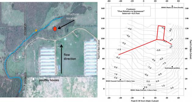
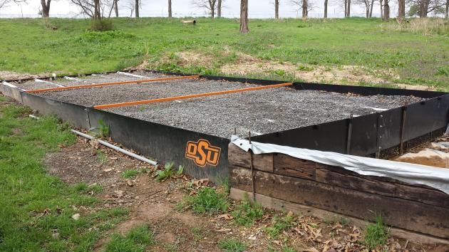
We constructed a P removal structure on a poultry farm in Eastern OK; this is a BMP that can remove dissolved P loading in the short term until soil legacy P concentrations decrease below levels of environmental concern. A P removal structure contains P sorbing materials (PSMs) and are placed in a location to intercept runoff or subsurface drainage with high dissolved P concentrations. As high P water flows through the PSMs, dissolved P is sorbed onto the materials by several potential mechanisms, allowing low P water to exit the structure. While they vary in form, P removal structures contain three main elements: 1) use of a filter material that has a high affinity for P, 2) containment of the material, and 3) the ability to remove that material and replace it after it becomes saturated with P and is no longer effective.

A site was identified which met all criteria for justification of construction of a P removal structure: 1) elevated dissolved P concentrations in runoff (>0.2 ppm), 2) hydraulic connectivity between the runoff/drainage produced and a surface water body, and 3) flow convergence: the site possessed potential to channel the runoff water to a single point in order to treat the water. This site was located on a poultry farm in Eastern OK.

The site was surveyed in order to obtain the necessary inputs for properly designing the P removal structure. This involved a basic NRCS survey to estimate watershed size, peak flow rates, and average annual runoff volume. In addition, several runoff grab samples were taken and analyzed for dissolved P. This information was used to determine the average annual dissolved P load, which was 45 lbs.

Knowing flow and P load parameters, we additionally chose P removal targets and desired lifetime of the structure. We chose to design a structure that would remove 20 lbs of dissolved P during the first year and be able to handle 700 gpm flow rate. Several hypothetical designs were made based on the available P sorbing materials (PSMs), such as drinking water treatment residuals, acid mine residuals, and gypsum. We chose to use a treated steel slag material as the PSM in the structure; this required about 35 tons of material.

After construction, the performance of the structure was monitored by measuring flow rates and dissolved P concentrations at the inlet and outlet. In addition, we developed software to aid in proper design of a site specific P removal structure using any PSM, in order to meet desired P removal goals and lifetime. Alternatively, this software can be used to predict the performance and lifetime of a P removal structure that has been already constructed. Licensing of software is available for private industry.

What have we learned?

p removal performance
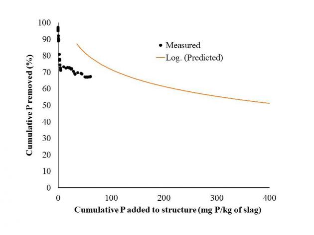
The P removal structure has removed approximately 67% of all dissolved P that has flowed into it over a 16-month time period. In addition, it has handled all flow volume from every event, including a runoff event that resulted in 600 gpm. That single event delivered 2/3 lb of dissolved P, in which the structure removed 66%. While the structure is removing P as predicted based on P loading, the structure has greatly outlasted the goal of removing 45% of cumulative dissolved P in one year. This is due to the below average rainfall received over the last two years.

We also learned about the potential positives and negatives of using certain PSMs. For example, although we could have used other PSMs, in much smaller quantities (2-10 tons) that would remove equal amounts of P, we would have had to build a structure that was much larger in surface area, due to the fact that the hydraulic conductivity of these PSMs is relatively low. It is also possible to build these structures with other materials for the frame, such as concrete, earth, or wood. Structures can be constructed in ditches or potentially in the subsurface to treat tile drainage.

Last, we have some sense of economics for P removal structures and the general cost of P removal compared to other BMPs.

Future Plans

phrog design softwareWe will continue to monitor the structure. In addition, we are cooperating with several people throughout the US in helping to design P removal structures. We are also releasing design software for licensing in an attempt to promote commercialization of this BMP through private industry. A NRCS standard is currently underway and the goal is for this BMP to become cost-shared. Last, we are continuing to investigate the economics of P removal structure over a large scale area.

Authors

Chad Penn, Associate professor of agricultural and environmental chemistry, Oklahoma State University chad.penn@okstate.edu

Josh Payne, Animal waste specialist, Oklahoma State University; James Bowen, graduate assistant; Stuart Wilson, senior research specialist, Oklahoma State University; Josh McGrath, associate professor of nutrient management, University of Kentucky

Additional information

Chad Penn; chad.penn@okstate.edu; 405 744 2746

www.p-structure.blogspot.com

http://www.jswconline.org/content/69/2/51A.full.pdf

http://pods.dasnr.okstate.edu/docushare/dsweb/Get/Document-9345/L-447%20Phosphorus%20Removal.pdf

Acknowledgements

NRCS for funding of this demonstration

The authors are solely responsible for the content of these proceedings. The technical information does not necessarily reflect the official position of the sponsoring agencies or institutions represented by planning committee members, and inclusion and distribution herein does not constitute an endorsement of views expressed by the same. Printed materials included herein are not refereed publications. Citations should appear as follows. EXAMPLE: Authors. 2015. Title of presentation. Waste to Worth: Spreading Science and Solutions. Seattle, WA. March 31-April 3, 2015. URL of this page. Accessed on: today’s date.

Using Solar Power to Provide Animals with Water while Protecting Water Quality


Why Consider Solar Power for Watering Livestock?

The purpose of this paper and presentation is to show how we have been using solar powered watering stations to provide a clean water supply to livestock while also protecting water resources. The project was started as a way to assist farmers who had received funding from some federal or state agencies to improve water quality on and through their land. One way to improve water quality is to fence livestock out of local waterbodies. As a result of this practice, the farmer may lose the ability to water his/her livestock.  A secondary reason for the project was, since livestock did not have direct access to water, the farmer had to either carry water to the watering stations or use some form of energy (diesel, gasoline, electric) to provided needed water.

What did we do?

To help solve the problem, funding was received from USDA-NRCS through the Conservation Innovation Grant Program (CIG) to install solar powered livestock watering stations. Farmers were selected based on information from NRCs field personnel, County Extension Agents and other groups working with farmers to fence livestock out of the waterbodies. The first steps were to visit with the farmers to determine need for a solar powered watering station.

Through a first set of questions, it was determined: 1) if the farmer needed the watering station; 2) where the watering station would be located; 3) was there an existing well and pump and what was the source of energy?;  4) what would be the preferred energy source based on available electricity; and 5) would there be a solar system that could be designed to meet the need of the farmer (an initial design).

To further discuss these steps, we looked to see if the farmer needed the watering station. Was there was a means to put in a limited access watering spot so water was still available on a limited basis and still help with protecting water quality? The location of the watering station was determined based on plans to rotationally graze the pasture where the livestock would be located. If the livestock were to be rotated through a number of different paddocks, the suggestion would be to locate the watering station in the center of a rotation. Alternatively, could a solar powered pumping system be located in one place and pump water to various watering stations on the property? The third aspect of the initial planning process was to determine if there was an existing well or pump. If there was an existing well and pump, what was the source of power for the pump? If diesel or gasoline was being used, what was the cost of such a system on an annual basis? The next aspect asked if there was available electric power for a pump? If the answer was “Yes, there is power less than one-quarter mile” then it was suggested the farmer consult with the local power utility to determine the cost of running power to the proposed pumping location. Another aspect of this step in the process was where would the water source be and would solar even be viable due to shade or tree cover? The last aspect of the determination of using solar power was the ability of us to design a system based on the number of livestock that had or needed to be watered and the depth of the well (if currently in place), expected depth to groundwater, height from a surface water source to highest and most distant watering station, and distance of having to run pipe from water source to most distant watering station. If after going through all of these aspects with the farmer, it was determined that a solar powered watering system was a good option for the farmer, we worked with him or her to fully design a solar powered watering system, ordered the solar components and helped the farmer install the system.

What have we learned?

From this project we have learned that there are some locations that are not good for a solar powered watering systems due to location, distance to available power and economics. Most of the times when the system was determined to be non-economical, it was due to there being electric power within a short distance of the proposed solar installation site. Short distance here is defined as any distance that makes running electricity to the proposed water source location economically preferable to that of installing solar power. Sometimes location was not a good fit in that there was very little open space to install a solar powered system for pumping the water. Another thing we have learned is that the solar powered system needs to be protected or at least in a location where livestock cannot get to the panels and control boxes. In cases where small livestock are being watered, having the solar panels on poles above their height can be beneficial in providing maintenance for grass control. However, for larger livestock, the support structure and solar panels themselves can become scratching posts which can result in broken solar panels. One other thing we have learned is that based on the needs or direction of the local NRCS working groups, solar powered watering systems may or may not be included in the cost share options for farmers.

Future Plans  

Future plans are to work with County Extension Agents, NRCS, farmers and other groups promoting the use of solar powered systems for watering livestock in areas where this technology can protect water quality.

Author     

Gary L. Hawkins, Water Resource Management and policy Specialist and Assistant Professor, University of Georgia, Crop and Soil Science ghawkins@uga.edu

Additional information                

For more information please contact ghawkins@uga.edu

Sun-powered water source. Angus Journal. July 2013. Anderson, B.B.

Acknowledgements     

Thanks to Mr. Gary Murphy for his assistance in installing and demonstrating the solar system in many different venues. Thanks also is extended to USDA-NRCS for funding the projects through the CIG program.

The authors are solely responsible for the content of these proceedings. The technical information does not necessarily reflect the official position of the sponsoring agencies or institutions represented by planning committee members, and inclusion and distribution herein does not constitute an endorsement of views expressed by the same. Printed materials included herein are not refereed publications. Citations should appear as follows. EXAMPLE: Authors. 2015. Title of presentation. Waste to Worth: Spreading Science and Solutions. Seattle, WA. March 31-April 3, 2015. URL of this page. Accessed on: today’s date.

Converting Manure, Food Wastes and Agricultural Production Wastes into Bio-Secure Fertilizer, feed, and/or beeding


Purpose

To find a way to completely eliminate bio-hazards in manure, food wastes, municipal sludge, and agricultural production wastes.

What did we do? 

We adapted existing dry extrusion technology to bio-hazard agricultural wastes. To test the hypothesis we developed [ Dry Extrusion Technology can be adapted to convert bio-degradable hazardous wastes into Bio-Secure class “A” fertilizer, feed, and/or bedding more economically, with less environmental impact, greater sustainability, and in less time with a smaller foot print]

Once we proved our Hypothesis we further developed the process to allow the technology to be utilized in a large stationary plant suitable for a large waste generator and in a portable plant that can be used to assist smaller waste generators, such as, most agricultural producers and smaller municipalities.

What have we learned? 

Our tests showed that we could validate our hypothesis by:

1) utilizing finely ground dry agricultural production wastes, mixed with the wet food and manure to reduce the moisture content of the wet wastes to a level compatible to the requirements of the dry extruder,
2) The Dry extruder effectively sterilized the wastes by high temperature, high pressure inside the extruder, and sudden drop in atmospheric pressure inside the cell walls of all the materials when exiting the Dry Extruder, thereby destroying the cell walls of not only the bio-mass materials but also of all micro organisms ova, and pathogens inside the final product.

Future Plans 

Develop new niche markets for agricultural waste generators by adding additional value to their wastes.

Authors

Joe E. Busby joebusby@wfeca.net 

Moses Braxton, Bill Ansley, William Andrews, Duncan Nesbit, and Dr. Carm Parkhurst

Acknowledgements

Insta Pro International, North Carolina State University

The authors are solely responsible for the content of these proceedings. The technical information does not necessarily reflect the official position of the sponsoring agencies or institutions represented by planning committee members, and inclusion and distribution herein does not constitute an endorsement of views expressed by the same. Printed materials included herein are not refereed publications. Citations should appear as follows. EXAMPLE: Authors. 2015. Title of presentation. Waste to Worth: Spreading Science and Solutions. Seattle, WA. March 31-April 3, 2015. URL of this page. Accessed on: today’s date.

Wood Chip Pad Winter Feeding Area as a New Livestock Manure Management System

Purpose

Over-wintering beef cattle on pastures in the Eastern half of the USA has been shown to increase runoff, sediment loss and nutrient transport. Traditional barn lot winter feeding areas, or ‘sacrifice’ areas, for beef cattle can be a significant source of nutrient and sediment pollution. Sustainable and affordable approaches are needed that effectively control manure nutrients during the winter feeding period, while ensuring a healthy and comfortable animal environment. The use of woodchips as a surface material for areas used to hold cattle during wet periods is practiced on a limited basis in Ireland, Scotland, and New Zealand. The application of this simple technology in the cool Eastern part of the US that has a humid climate, has potential to improve animal comfort and health, protect winter pastures, and reduce the environmental impact of winter feeding and loafing areas.

Figure 2. Woodchip Pad Profile

What did we do?

Beef cattle producers in United Kingdom, Ireland and New Zealand have shown a positive conservation effect using out wintering pads constructed with wood chips, allowing the pastures to be destocked. Out Wintering Pads (OWPs) are outside loafing areas for cattle. OWPs are typically constructed adjacent to a concrete feeding area and a watering facility. The OWP design allows for 150 square feet per cow. The chip size is critical for proper functioning of the manure storage system. Use of fist to palm sized chips are recommended to allow dung to filter into the pad. Smaller chips can be used but will need to be renewed sooner. Manure is worked down below the surface of the pad by the cattle’s hoof action. Initial depth of chips needs to be no less than 12 -15 inches deep. The site must be prepared with a drainage system using drain pipes every 10 feet to prevent moisture accumulation within the OWP (Figure 2). This effluent must be managed with a storm water retention pond and vegetated filter strip.

Figure 1. Initial woodchip pad developed in West VirginiaWhat have we learned?

Two woodchip-surfaced heavy use areas have been installed and monitored in West Virginia. The first was installed on a private farm with a cow/calf enterprise in Northern WV during 2011 (Figure 1).

The design criteria were adopted from a guidance document developed by the Irish Department of Agriculture and Food. This wood chip pad was placed adjacent to a USDA NRCS roofed winterfeeding area and roofed manure storage. Woodchip quality was determined and temperature and precipitation monitoring occurred for a 23 month period including two winter stocking periods. Effluent water quality grab samples were taken during that monitoring period. A second chip pad was constructed in WV on the West Virginia University (WVU) Animal Science Experiment Station Farm during 2014. This area consists of two loafing paddocks, one constructed with single species white oak wood chips and the other with mixed hardwood chips made up primarily of mixed yellow-poplar and oak. Bench scale columns with various configurations of thermally treated wood chips were evaluated in 2014.

Column Study Setup

  • PVC pipe (8-inches in diameter) columns
  • Runoff water was collected from the waste water storage tank at WVU’s Animal Science Farm
  • Gravel placed in each of the columns to a height of 12 inches (304.8mm) and then each column was packed with 12 inches (304.8mm)  of varying media (Figure 3)

Figure 3. Column study biomass combinations

  • Three rain events (1cm, 2cm, and 3cm) (with 96 hours between events) were passed through the columns
  • Each of the columns were then cleaned and re-packed and subjected to waste water to a depth of 18 inches (459 mm) for 48 hours
  • Pre- and post-water samples were collected to test for phosphorous (P), ammonia, and Total Kjeldahl nitrogen (TKN) 

Biomass Media Performance – Rain Events

  • Mixed hardwood chips had superior P concentration reduction compared to white oak chips, but lower Total TKN reduction (Figure 4)
  • Gravel outperformed the biomass media filters (Figure 4)
  • Of the biomass media, the WO + TR 275OC/BC media showed the highest % reduction of P, TKN, and Ammonia (Figure 4)

Biomass Media Performance – 48 Hour Hold

  • White oak chips had better TKN reduction than mixed hardwood chips, but lower P reduction  (Figure 5)
  • Mixtures containing biochar resulted in greater pollutant reductions than torrified treatments without biochar (Figure 5)
  • The WO + TR 275C/BC media showed the highest % reduction of TKN and Ammonia, but not the highest P % reduction (Figure 5)

Figure 4. Percent Reduction: Rain Event Study

Figure 5. Percent Reduction: 48 Hour Hold Study.

The biomass mixes that have demonstrated the best performance are being added as treatments in small cell areas on the WVU woodchip heavy use area. The treatment cells are being monitored for runoff flow amounts and water quality.

Future Plans  

Further research is needed to determine optimum chip species and chip size for moisture retention and nutrient capture capabilities. Development of complimentary systems to treat the effluent produced from periods of runoff are needed as vegetated treatment areas may not function well during the winter when WV soils are typically saturated and runoff occurs instead of infiltration.

Authors     

Tom Basden, Extension Specialist, West Virginia University tom.basden@mail.wvu.edu

Joshua Faulkner, UVM and David DaVallance, WVU

Additional information             

Tom Basden 1060 Agricultural Sciences Building Morgantown WV 26506

The authors are solely responsible for the content of these proceedings. The technical information does not necessarily reflect the official position of the sponsoring agencies or institutions represented by planning committee members, and inclusion and distribution herein does not constitute an endorsement of views expressed by the same. Printed materials included herein are not refereed publications. Citations should appear as follows. EXAMPLE: Authors. 2015. Title of presentation. Waste to Worth: Spreading Science and Solutions. Seattle, WA. March 31-April 3, 2015. URL of this page. Accessed on: today’s date.

Supporting Small-Scale Poultry and Livestock Businesses

Waste to Worth: Spreading science and solutions logoWaste to Worth home | More proceedings….

Why Work With Small Poultry and Livestock Operations?

Understand the business planning and development issues confronting small-scale livestock and poultry producers.

What Did We Do?

Colorado State University has been building educational programming to benefit small-scale crop and livestock producers across the state since 2007.  The Colorado Building Farmers and Ranchers program uses a classroom, experiential learning and community-building approach to help smaller-scale and new agricultural producers build their businesses in a profitable, safe and sustainable manner. To date, we have graduated more than 300 producers, 65% of whom have completed business plans to expand or develop their agricultural business. These producers are primarily characterized by their focus on direct marketing, and many are located relatively close to urban areas; locations that provide both marketing opportunities as well as production constraints. The classroom education takes place over 8 weeks and helps producers build sustainable business plans, and develop a network of producers and technical assistance providers (e.g. NRCS, FSA, county planning staff).  Topics covered include developing a production plan, recordkeeping, pricing, risk management, and on-farm food safety.  In addition, since small-scale livestock production is a more complex business model, we have built a curriculum that guides producers through all the business planning considerations necessary to start and operate a profitable livestock operation: from acquiring poultry, sheep or goats, to health and environmental issues, to processing and creating a unique market niche.

What Have We Learned?

Given that smaller or more diversified poultry and small ruminant operations may be trying to maintain a greater number of enterprises on one farm or operation, it may be more difficult for those producers to stay on top of good management practices, as well as any requirements necessary to remain in good standing with local government and marketing partners. For example, these small-scale operations may be maintained on a limited number of acres, thus requiring very careful land and animal management.  Additionally, many smaller-scale operations are located in areas where agriculture is not the primary land use.  Such operations may be in the urban-rural interface, the suburbs or even in towns or cities.  The research for this curriculum provided a basic overview of production, management and marketing considerations and opportunities for smaller-scale poultry and small ruminant production, and a means to discuss the relationship between resource stewardship and long-term business viability. We examined, in particular, emerging niche market opportunities and some of the costs and benefits inherent to pursuing those newer markets, finding that the costs and management skills required make it extremely difficult to operate a commercially viable small-scale livestock business in an urban area.

Future Plans

Next steps involve developing enterprise budgets with different numbers of poultry and small ruminants to understand the point at which these businesses become financially viable. This is important for helping prospective new livestock enterprises to truth their business plans, based on realistic assumptions.

Raising Poultry for Profit Video

Raising Sheep and Goats for Profit Video

Authors

Martha Sullins, Extension Regional Specialist, Colorado State University Extension, Martha.sullins@colostate.edu

Additional Information

Acknowledgements

David Weiss and Dawn Thilmany (Department of Agricultural and Resource Economics, CSU), Blake Angelo (Urban Ag Educator, Denver/Jefferson Counties, CSU Extension),  Marisa Bunning (Department of Food Science and Human Nutrition, CSU); Thomas Bass (Montana State University).

The authors are solely responsible for the content of these proceedings. The technical information does not necessarily reflect the official position of the sponsoring agencies or institutions represented by planning committee members, and inclusion and distribution herein does not constitute an endorsement of views expressed by the same. Printed materials included herein are not refereed publications. Citations should appear as follows. EXAMPLE: Authors. 2013. Title of presentation. Waste to Worth: Spreading Science and Solutions. Denver, CO. April 1-5, 2013. URL of this page. Accessed on: today’s date.

Feasible Small-Scale Anaerobic Digestion – Case Study of EUCOlino Digestion System.


* Presentation slides are available at the bottom of the page.

Waste to Worth: Spreading science and solutions logoWaste to Worth home | More proceedings….

Abstract

While large-scale farms have typically been the focus of anaerobic digestion systems in the U.S., an emerging need has been identified to serve smaller farms with between 50 and 500 head of cattle. Implementing such a small, standardized, all-in-one system for these small farm applications has been developed. Small-scale digesters open the playing field for on-farm sustainability and waste management.

Unloading the first biodigester unit.

This presentation on small-scale digestion would discuss the inputs, processing, function, and outputs of BIOFerm™ Energy Systems’ small agitated plug flow digester (EUCOlino). This plug-and-play digester system has the ability to operate on dairy manure, bedding material, food waste, or other organic feedstocks with a combined total solids content of 15-20%. A case study would be presented that describes the site components needed, the feedstock amount and energy production, as well as biogas end use. Additional details would include farm logistics, potential sources of funding, installation, operation, and overall impact of the project.

This type of presentation would fill an information gap BIOFerm™ has discovered among dairy farmers who believe anaerobic digestion isn’t feasible on a smaller scale. It would provide farmers who attend with an understanding of the technology, how it could work on their specific farm and hopefully reveal to them what their “waste is worth”.

Why Study Small-Scale Anaerobic Digestion

To inform and educate attendees about small-scale anaerobic digestion surrounding the installation and feasibility of the containerized, paddle-mixed plug flow EUCOlino system on a small dairy farm <150 head.

Biodigester unit being installed at Allen Farms.

What Did We Do?

Steps taken to assist in financing the digestion system include receiving grants from the State Energy Office and Wisconsin Focus on Energy. Digester installation includes components such as feed hopper, two fermenter containers, motors, combined heat and power unit, electrical services, etc…

What Have We Learned?

Challenges associated with small project implementation regarding coordination, interconnection, and utility arrangements.

Future Plans

Finalize commissioning phases and optimize operation.

Authors

Amber Blythe, Application Engineer, BIOFerm™ Energy Systems blya@biofermenergy.com

Steven Sell, Biologist/Application Engineer, BIOFerm™ Energy Systems

Gabriella Huerta, Marketing Specialist, BIOFerm™ Energy Systems

Additional Information

Readers interested in this topic can visit www.biofermenergy.com and for more information on our plants, services and project updates please visit us on our website at www.biofermenergy.com. You will also see frequent updates from us in industry magazines (BioCycle, REW Magazine, Waste Age). BIOFerm will also be present at every major industry conference or tradeshow including the Waste Expo, Waste-to-Worth and BioCycle– stop by our booth and speak with one of our highly trained engineers for further information.

The authors are solely responsible for the content of these proceedings. The technical information does not necessarily reflect the official position of the sponsoring agencies or institutions represented by planning committee members, and inclusion and distribution herein does not constitute an endorsement of views expressed by the same. Printed materials included herein are not refereed publications. Citations should appear as follows. EXAMPLE: Authors. 2013. Title of presentation. Waste to Worth: Spreading Science and Solutions. Denver, CO. April 1-5, 2013. URL of this page. Accessed on: today’s date.