This webinar will explore how the 360Rain autonomous irrigation system is being used as a new tool for manure management. By enabling in-season manure application, 360Rain opens opportunities to better match nitrogen availability with crop uptake, reduce manure storage time (and associated methane emissions), and even provide supplemental irrigation. This presentation was originally broadcast on September 26, 2025. Continue reading “Rethinking Manure Management with 360Rain: Expanding Application Windows and Improving Nutrient Use Efficiency”
Nutrient and Water Quality Outcomes from In-Crop Manure Application to Corn
Purpose
Sidedressing corn with liquid manure is a better application timing to utilize manure nitrogen efficiently. A percentage of fall-applied nitrogen is converted to nitrate-N. The amount converted depends upon soil temperatures and days to incorporation after land application. This nitrate is environmentally lost through leaching or denitrification before corn planting and nutrient uptake. While the total corn nitrogen application rate is reduced by an N credit or measure of soil nitrate through a pre-sidedress nitrogen test, commercial fertilizer will often be applied at corn sidedress time. The combined fall manure and fertilizer N applied results in increased total nitrogen, increasing environmental N loss potential. In-crop manure application has the advantage that any ammonium N applied can offset the total N requirement of the corn crop.
The experimental objectives were to determine the economic, agronomic, and environmental outcomes of in-crop manure application versus a traditional fall manure application.
What Did We Do?
A trial comparing fall to in-crop liquid manure application to corn was established in the fall of 2019 at a USDA-ARS paired Edge-of-Field monitoring site in the Western Lake Erie Watershed. The trial used a before/after impact experimental design. Field one had fall-applied manure, then used UAN at corn sidedress time. The second field had only swine manure applied at corn sidedress timing. Data collected included corn yield, soil test, tissue test, imagery, and nutrient loss through tile and surface runoff. Aerial imagery utilized Normalized Differential Red Edge (NDRE) imagery measure on a 0-1 scale to quantify plant heath.
What Have We Learned?
The total applied nitrogen with fall manure/UAN application was 516 pounds per acre compared to 341 pounds per acre for in-crop manure application. Corn yield was improved by 17 bushels per acre with the in-crop manure application despite a dryer than normal production year where the treatment total yield was 136 bushels per acre. Tissue tests taken at R1 were similar between the two treatments with %N and %P lower than desired ranges. In-crop manure application resulted in a 0.63 NDRE index compared to a 0.60 NDRE index for fall manure/UAN application, indicating better plant health. The in-crop manure application had higher equipment and labor costs that were offset by reduced nutrient cost, plus higher yields improving net return by $95 per acre.
The applied nitrogen not recovered in the grain was 437 and 250 pounds per acre for the fall manure/UAN and in-crop manure application, respectively. Soil samples using a 0-12 core depth were taken after application (June), after harvest (November), and spring of the following year (March and May). Nitrate and phosphorous levels were higher for the in-crop application for all sampling periods prior to the May sampling. By May soil test levels were equal for both nutrients. Both nitrate and phosphorous levels in the 0-12 zone were within expected ranges. The estimated in-crop manure application effects had mixed results for tile and surface water quality outcomes measured in pounds per acre. For tile water DRP (-5%), Nitrates (-35%) were reduced while Total P (7%) increased. The surface water had lower nitrate (73%) but higher DRP (148%) and Total P (43%). Tile water is a greater pathway for offsite water movement.
Future Plans
Wheat was planted after soybean in fall 2021. The anticipated comparison is in-crop manure application compared to fall-applied manure/topdress fertilizer to supply needed N. A second corn in-crop to fall-applied manure/commercial fertilizer comparison is planned for the 2023 crop year. These projects are cooperation with USDA-ARS Soil Drainage Unit and Blanchard Valley Demo Farms.
An Ohio State University Extension initiative is looking at fall applied versus in-crop manure application at 10 paired field sites in 2022 and 2023. A second set of field trials are N rate trials 0-250 pounds of N in manured fields with 5 sites in 2022 and 2023.
Authors
Greg LaBarge, Field Specialist, Agronomic Systems, Professor, Ohio State University Extension
Corresponding author email address
labarge.1@osu.edu
Additional authors
Kevin King, Research Leader and Agricultural Engineer, USDA-ARS Soil Drainage Unit, and Jed Stinner, Hydrologic Technician, USDA-ARS Soil Drainage Unit
Acknowledgements
Blanchard Valley Demonstration Farms
Going the distance: considerations for the use of manure pipelines
In this webinar, presenters share tips on what to look for, how to monitor your system, and what maintenance is needed for manure pipelines. This presentation was originally broadcast on February 18, 2022. Continue reading “Going the distance: considerations for the use of manure pipelines”
Grid Soil Sampling to Guide Manure Application
Why Consider Grid Sampling for Manure Application?
Grid soil sampling for phosphorus and potassium can identify areas in fields with nutrient deficiencies and other areas with sufficient or excess nutrients. Nutrient maps can be used to define areas for manure application or exclusion, using supplemental fertilizer where manure is not applied or does not meet the crop requirements. The overall effect is to increase the fertilizer-replacement value of the manure, conserving its use for nutrient deficient fields and field areas. Related: LPELC Manure Nutrient Management
Each of the case studies was conducted on a Minnesota farm and presents the method to:
- determine crop nutrient needs
- create manure application and exclusion zones from nutrient maps
- estimate the value of manure under whole-field vs zoned application, and
- evaluate practices to reduce off-site soil and nutrient loss for the specific field analyzed.
Videos
- Part 2: Case study of grid soil sampling for manure application on a dairy farm
- Part 3: Case study of grid soil sampling for manure application on a hog farm
- Part 4: Four brief examples of grid soil sampling for manure application on livestock farms
- Part 5: Nutrient availability from manure and crop nutrient guidelines in Minnesota
- Part 6: Problems of excess or poorly applied phosphorus from manure
The case studies do not discuss variable rate manure application, but do assume capability for supplemental fertilizer application, with or without variable rates.
For More Information
https://portal.nifa.usda.gov/web/crisprojectpages/0099228-agricultural-impacts-on-water-quality.html
Les Everett, Agronomist, University of Minnesota Water Resources Center evere003@umn.edu
Liquid Manure Storage Treatment Options, Including Lagoons
A vital component of liquid livestock and poultry manure collection and handling systems is storage capacity for the collected manure and associated material(flush water, wasted feed, etc.). This manure storage capacity is typically in the form of under-floor pits or outside storage tanks or ponds and/or treatment lagoons. These structures accumulate collected wastes and allow the waste management system operator to move away from a “daily scrape (collect) and haul” situation. This reduces time and labor needed for final disposition (either land application or off-farm “value-added” processing) of these manure accumulations.
What Is a Liquid Manure System?
“Liquid” livestock manure collection and handling systems are actually “fluid” livestock manure collection and handling systems. These systems are selected based upon the consistency or “thickness” of the manure and its flow characteristics. Manure flow characteristics are highly dependent on “solids content” or “percent solids” of the manure volume.
Liquid manure storage volume size depends on the amount of time in a year that is not available for land application or other manure utilization strategies. This is the design storage period. Land application time depends on growing season of the target crop(s) and local weather. Manure storage volume should be emptied by the end of the design storage period to be able to hold the expected amount of manure accumulation during the next storage period.

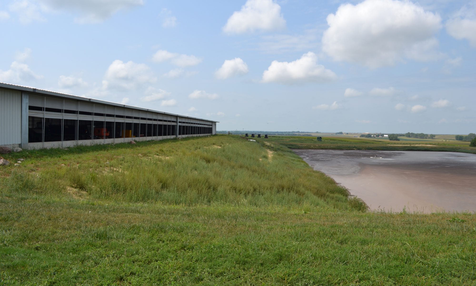
Earthen storage structure with artificial liner (from Proper Lagoon Management to Reduce Odor and Excessive Sludge Accumulation).
This web page deals with two general categories of liquid systems:
- Pits or slurry systems for storage only
- Lagoons with both slurry/wastewater storage and treatment (see National Center White Paper summary, Manure Management Strategies).
Types of Manure
“As-excreted” livestock manure moisture content changes as it moves through the collection process into storage. Liquid collection and handling systems add waste drinking water, wash water, flush water, rain, and stormwater runoff, lowering solids content below the 15% level typically used to define “solid” manure. A manure volume of 5 to 15% solids is “slurry” manure, with consistency and flow characteristics similar to thick chocolate malt. Manure volumes with 0 to 5% solids content have consistency and flow characteristics similar to water.
What Is the Difference Between Storage and Storage With Treatment?
Contrasting storage and storage w/treatment, a manure containment structure which is emptied at the end of the storage period is essentially a storage structure. A lagoon has storage volume but will also have a permanent pool for residual treatment volume that provides a bacterial seed bed for continual bacterial action at an elevated level. This permanent pool is not considered in the design of a structure used for storage alone. Essentially whatever goes into a properly managed storage structure is what is pumped out. A lagoon, however, is designed to promote decomposition of organic matter entering the lagoon. For this reason, a lagoon is much larger than a storage pond.
Management of Lagoons
A manure containment structure which is not emptied at the end of the storage period is being operated as a lagoon, whether designed that way or not. Storage operated in this manner becomes a smelly, overloaded lagoon. Generally, when agitation is used to put settled or floating solids into suspension before pumping out the effluent, or the slurry, the structure is being operated as storage.
Digested solids do accumulate in a lagoon and should be removed once every ten or more years, or as specified by the system design to restore residual treatment volume. In rare circumstances, particular to specific lagoons approaching this restoration point, some engineers recommend some agitation during normal pumpout to remove some of this accumulation. Routine pumping from the storage volume portion of a lagoon involves only wastewater (<5% solids) and requires no agitation.
Related Web Pages
- Earthen Manure Containment Structures
- Role of Solid Liquid Separation in Manure Storage
- Liquid Manure Storage Ponds, Pits, and Tanks
- Liquid Manure Treatment Lagoons
Recommended Educational Resources
National Center for Manure and Animal Waste Management white paper summary, Manure Management Strategies published by North Carolina State University. A two page Executive Summary is available. The full white paper can be ordered from Midwest Plan Service, Iowa State University.
Page Managers: Ted Tyson, Auburn University, tysontw@auburn.edu and Saqib Mukhtar, Texas A&M University, mukhtar@tamu.edu .
Earthen Manure Containment Structures
All articles about:
Contents |
Siting an Earthen Manure Storage Structure
Because earthen manure and process generated wastewater storage structures are generally less expensive to build than above-ground metal or concrete tanks or below-ground concrete tanks, most operators choose earthen storage construction (ponds) where possible. To minimize potential for surface and ground water contamination, storage structures are located at least 150 feet from any uphill well, 500 feet from other wells, and 50 feet from the manure production/collection area (typically, animal housing). Check state and/or local regulations for specific setback distances for manure collection and storage structures in your area.
For gravity transfer of collected manure wastes to storage pond and possible settling basin use, sewer lines are generally installed on 1% slopes and sized for flow velocities greater than 2 feet per second. A waste storage pond should not be located in a flood plain nor should the bottom of the pond be constructed to a depth below the underground water table unless curtain drains or interception drains are installed around the perimeter of the pond at least 1 foot below the pond bottom.
Standards for Earthen Manure Storage Structures
Properly designed, installed and operated according to accepted engineering standards defined by USDA-NRCS and ASABE publications listed below under “Recommended Reading on Earthen Manure Containment Structures”, earthen manure structures should pose little risk to water quality.

Geology and Soils
Geologic conditions and treatments are determined from county soil surveys and performance of other waste storage ponds in the area and an on-site inspection. A backhoe under the direction of an experienced engineer, geologist, or soil scientist is one of the best subsurface soil investigation tools available.
An on-site subsurface soils investigation determines if the planned manure storage site has shallow soil over coarse sand and gravel, creviced limestone, or permeable bedrock. If any of these conditions exist, construction procedures and materials to prevent seepage to ground water, such as clay liners, geotextile or fabric liners, or concrete, are used.
As part of the animal waste management technical assistance program, Natural Resources Conservation Service (NRCS) currently offers on-site soils and geologic investigation assistance for animal waste management structures. NRCS should be contacted for assistance. Corrective treatments at some locations could be so costly that aboveground storage may be required or a waste management system at the site may be totally impractical. This could force moving an existing animal facility to a more suitable location and should definitely be a significant part of the site investigation process for new animal facility installations.

Related Web Pages
- Liquid Manure Storage Treatment Options, Including Lagoons
- Role of Solid Liquid Separation in Manure Storage
- Liquid Manure Storage Ponds, Pits, and Tanks
- Liquid Manure Treatment Lagoons
Recommended Reading on Earthen Manure Containment Structures
- American Society of Agricultural and Biological Engineers On-Line Technical Library, ASABE Technical Library EP393.3 Manure Storages
- American Society of Agricultural and Biological Engineers On-Line Technical Library, ASABE Technical Library EP403.3 https://elibrary.asabe.org/abstract.asp?search=1&JID=2&AID=36429&Abstract=403.htm&CID=s2000&T=3&urlRedirect=[anywhere=&keyword=&abstract=&title=on&author=&references=&docnumber=&journals=All&searchstring=Design%20of%20Anaerobic%20Lagoons%20for%20Animal%20Waste%20Management&pg=&allwords=&exactphrase=Design%20of%20Anaerobic%20Lagoons%20for%20Animal%20Waste%20Management&OneWord=&Action=Go&Post=Y&qu=]&redirType=newresults.asp Design of Anaerobic Lagoons for Animal Waste Management]
- Natural Resources Conservation Service National Engineering Handbook Part 651, Agricultural Waste Management Field Handbook, Chapter 10 Agricultural Waste Management System Component Design
- Livestock and Poultry Environmental Stewardship Curriculum LPES Lesson 20: Planning and Evaluation of Manure Storage
Page Managers: Ted Tyson, Auburn University, tysontw@auburn.edu and Saqib Mukhtar, Texas A&M University, mukhtar@tamu.edu .
Liquid Manure Sampling Procedures
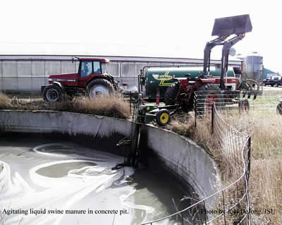
When testing manure, your nutrient management plan is only as good as your ability to obtain a representative sample. In liquid manure storage, agitation is critical to spreading uniform manure and to getting a representative sample. Agitating for 2-4 hours is the minimum. Depending on the type of storage longer agitation times may be required. The agitation for sampling should be similar to the agitation done when the storage is emptied. For this reason the most practical time to sample is when the storage is being emptied for field application.
If the storage is not adequately agitated there will likely be stratification. The figure below illustrates how manure analysis can vary within a storage without adequate agitation. In this example manure in the last 15 loads spread from this storage has 2 to 3 times more phosphorus than in the first 45 loads spread. If the storage is known to be stratified, separate samples should be taken as the manure consistency changes during emptying.
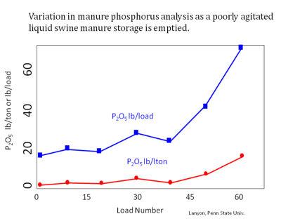
cc2.5 Les Lanyon
Sampling As Manure Storage Is Emptied
Agitate the storage thoroughly before sampling. Use a bucket to collect at least 5 samples during the process of loading several spreader loads and save them in the bucket. When all of the samples are collected, thoroughly mix the samples and take a subsample from this to fill the lab manure test container. When filling containers with liquid manure never fill the container more than ¾ full. If samples are collected over a several hour period, the bucket with manure sample should be stored on ice to limit ammonia losses.

Sample Manure When Pumping From Storage. Photo courtesy of Ontario Ministry of Agriculture, Food and Rural Affairs. Photo Source: http://www.thecattlesite.com/articles/1307/sampling-liquid-manure-for-analysis
Sampling From the Manure Storage
Picture Source: http://www.extension.iastate.edu/pages/communications/epc/Winter02/manure.html
Sampling a storage directly is much more difficult and likely to result in more variable results than sampling as the manure is loaded into the spreader. Agitate the storage thoroughly before sampling. Use a small bucket or tube to collect at least 5 samples from different locations in the storage. Combine these samples in a bucket and thoroughly mix the samples and take a subsample from this to fill the lab manure test container. When filling containers with liquid manure never fill the container more than ¾ full.
Liquid Manure Sampling Video
This video from the Iowa Learning Farms Project shows two sampling techniques for liquid manure storage prior to agitation. As indicated above, samples of agitated liquid manure should be obtained when possible, but in cases where the information from the lab analysis (which can take several days) is needed before manure can be applied to crop land.
Part 2: Sampling Liquid Manure
Sampling Manure During Application
This method is good for irrigated manure. Place buckets around the field to catch manure from the spreader or irrigation equipment. Place these to collect manure from more than one spreader load. Combine and mix the manure collected from different locations, and take a subsample from this to fill the lab manure test container. This method may give you “crop available ammonia nitrogen” as any ammonia losses may have already occurred prior to reaching bucket. What reaches the bucket is likely to soak into the soil and be available to the crop.
Related Web Pages
Overview of Manure Testing
- Step 1. Manure Sampling
- Solid Manure Sampling Procedures
- Liquid Manure Sampling Procedures (you are here)
- Step 2. Manure Test Results
- Step 3. Total and Available Nutrients
- Step 4. Manure Test Record Keeping
Page Authors: Douglas Beegle, Penn State University and John Peters, University of Wisconsin
Calibrating Liquid Manure Application Equipment
Types of Liquid Manure Application Equipment
Liquid manure application equipment includes tankers (sometimes called honey-wagons) and hose-drag (also referred to as drag-hose) systems. Depending upon the type of liquid application system being calibrated, calibration may require weighing the tanker, recording the time to empty a load, measuring application spread width and length and/or recording equipment speed. Also, with some calibration methods, determination of manure density is required.
Related: Calibrating solid manure spreaders and irrigation equipment.
Important Factors For Making Calibration Calculations
Normally calibration requirements are specific to the equipment, i.e. one piece of equipment needs only to be calibrated once during the calibration interval, often annually. However, it is a good idea to calibrate equipment that may be used under different conditions. For instance, adding more hose to a hose-drag system when moving from one field to the next can increase friction loss and alter manure flow rates though the applicator. It may also be valuable to calibrate for multiple travel speeds, each representing a different application rate. This allows one to select an application rate that most closely matches the nutrient requirements of individual fields or crops.
It is important to select the calibration procedure that is consistent with your manure analysis. For instance some analysis reports nutrients in a weight per volume measure (e.g. pounds per thousand gallons) while some analysis is provided on a weight per weight basis (e.g. pounds per ton). Calibration of liquid tanker spreaders can be done by weighing a load or knowing the capacity (volume) of the spreader as specified by the manufacturer. Conversion between volume and weight may be done by determining the manure density.
By knowing the spreader capacity, distance traveled to empty the spreader, and width of spread pattern (or distance you move laterally with each pass through the field), a fairly simple estimate of application rate can be made. This should be repeated several times to determine an average application rate each manure source. The speed of the tractor can be varied to adjust the application rate to achieve the planned application rate(s). The general procedure for calibrating a liquid manure tanker spreader is illustrated in the following file Liquid Spreader Calibration.
Hose drag type systems are calibrated by measuring tractor speed, flow rate of the manure through the system and effective width (distance between passes). These factors allow conversion to volume of manure over area applied, e.g. gallons per acre.

Calibration of hose-drag (drag-hose) equipment requires measurement of (a.) tractor speed, (b.) spread width (We in illustration) and (c.) flow through the hose. Photo: Garry Grabow, All Rights Reserved.
Recommended Educational Resources
- Lesson 36 Calibrating Manure Application Equipment from the Livestock and Poultry Environmental Stewardship (LPES) Curriculum offers an overview of the different equipment used to land apply animal manure.
- Calibrating Liquid Tank Manure Applicators, Iowa State University Extension provides a step-by-step guide to calibration based upon load size and application area.
- Field Calibration Procedures for Semi-Solid Animal Waste Application Equipment – Load-Area Method, North Carolina Cooperative Extension is similar to the previous publication but provides a field sheet that incorporates speed and other equipment settings.
- Field Calibration Procedures for Hose-Drag Wastewater Application Equipment, North Carolina Cooperative Extension shows how to field calibrate both boom-type and incorporation-type liquid spreaders that use a hose-drag type system.
Author: Garry Grabow, North Carolina State University Reviewers: Marsha Mathews, University of California-Davis, Rick Koelsch, University of Nebraska, Doug Beegle, Pennsylvania State University
Calibrating Irrigation Equipment for Manure Application
Irrigation equipment can be used to land apply manure with a solids content of up to 2-3 percent depending upon the type of equipment used and nozzle size. The types of systems typically used are stationary (also called solid-set), traveling guns, and center pivots. Irrigation equipment is typically used to land apply liquid manure from anaerobic lagoons and runoff holding ponds. If applied manure is undiluted, calibration requirements may differ slightly from those systems using diluted manure. If manure is diluted with freshwater, nutrient concentration must be adjusted by the dilution ratio when calculating nutrient rates. Always check with your state regulatory agency for calibration and reporting requirements.
Related: Calibrating solid manure spreaders and irrigation equipment.
As with the other types of equipment used for land applying manure, calibration consists of verifying application rates and application uniformity. Application rate and uniformity is measured by collecting applied manure in rain gages that are placed in a line for traveling gun and center pivot systems or in a grid for stationary systems. Systems using undiluted manure may require measurement and reporting of application rate from the gun or nozzle and not what is collected in a rain gage if plant available nutrients are calculated to include evaporative losses and volatilization.
If measuring application rate from the gun, a flow meter or pressure measurement at the nozzle and a manufacturer’s performance chart for the gun/sprinkler and nozzle will be required. Collected depths are used to calculate commonly-used measures of irrigation equipment uniformity such as the Christiansen uniformity coefficient (CU or Uc) or distribution uniformity (DU). Details of how to setup uniformity evaluations and calculate measures of uniformity and application rates are given in the links in a paragraph at the end of this document.
Uniformity of irrigation-type equipment can be affected by:
- Operating pressure
- Nozzle condition
- Pump impeller condition
- Wind

It is important that these types of systems be operated as designed. Normally this means that pressure and flow rate should be field-verified in the calibration procedure and compared to the design values or the ranges recommended by the manufacturer. Pressure should always be measured at the nozzle, not at the pump or other location. Pressure can be measured either with a pressure gauge mounted on the sprinkler riser or mounted on the gun body (for big guns) or measured using a pitot tube placed directly in the nozzle stream. For center pivots with drop nozzles, pre-set pressure regulators are normally located on the drop tubing, so nozzle pressure is known. In addition to pressure and flow rate measurement, the wetted diameter of the sprinkler or gun (for solid set and traveling gun systems respectively) should be measured.
It is generally recommended that flow rates be within 10 percent of the design rate, and that wetted diameter be within 15 percent of that specified in the manufacturer’s chart at the measured nozzle pressure. Flow rates may be obtained either by using a flow meter or by using values obtained from the manufacturer’s chart at the measured pressure. For animal waste systems, flow meters are normally temporarily placed in the main irrigation line either in-line or temporarily strapped on depending upon the type of flow meter used.
Adjustments to achieve the proper application rate and uniformity include adjusting operating pressure, travel speed (for traveling gun or pivot systems), replacing worn nozzles, and operating systems when there is little wind. Changes in equipment (e.g. nozzle size) should not be done without consultation with an irrigation specialist.
Recommended Educational Resources
- Lesson 36 Calibrating Manure Application Equipment from the Livestock and Poultry Environmental Stewardship (LPES) Curriculum offers an overview of the different equipment used to land apply animal manure, including irrigation equipment.
- North Carolina Cooperative Extension has a series of publications that can be used to evaluate application uniformity for stationary, traveling systems, and center pivot or linear move systems.
- Calibration of Lagoon Irrigating Equipment from University of Missouri Extension provides information on how to calculate application rates and depths for stationary and traveling type systems.
Author: Garry Grabow, North Carolina State University Reviewers: Marsha Mathews, University of California-Davis, Rick Koelsch, University of Nebraska
Photo: CC 2.5 Charles Fulhage or Joe Harner
Liquid Manure Storage Ponds, Pits, and Tanks
Waste storage pits and indoor tanks are generally under-floor inside the dairy, swine (and sometimes poultry) housing. Waste storage ponds and above ground storage tanks are fenced and posted to keep young children, livestock, and other unauthorized visitors away. Pond banks are seeded or sodded with a good grass cover to prevent soil erosion and mowed regularly to control grass and weed growth.
Recommendations for siting, design, and construction of manure storage units are provided in ASABE Technical Library EP393.3 Manure Storages. These recommendations are for both earthen and fabricated structures.
Storage Volume
Storage volume considerations include daily animal manure and related wash/flush water inputs. Dairy cattle generally generate larger manure volumes per live weight than swine, beef, or poultry. A mature dairy cow weighing 1,400 pounds can generate around 14 gallons (about 120 pounds or 1.9 cubic feet) of feces and urine each day with an average as-excreted solids content of around 12 percent.
The total excrement for cows housed in freestall total confinement, along with milking wash wastes would bring the total to more than 2.5 cubic feet per cow per day. For 100 cows, this is nearly 9 tons and 9+ cubic yards of manure per day. For cows on pasture part-time, manure handling and storage needs would be less and in direct proportion to actual confinement time. A 100-cow herd on half-time pasture would accumulate nearly 5 cubic yards (4.5 tons) of manure per day in confinement, including milk wash wastes. This daily manure volume for the confinement operation is multiplied by the planned storage period days to get the manure storage volume for the planned storage period.
Outdoor Storage Pond Volume
Outside storage pond or uncovered tank volume must also include expected rainfall minus evaporation from the storage surface. In high rainfall areas like the Southeastern US this could be 12 to 14 inches annually. In all geographical locations, this is based on the planned storage interval worst case and on local rainfall and evaporation figures. Volume must also include space for the 25-year-24-hour rainstorm event and any resulting watershed runoff into the pond. Roof and other rainfall runoff may or may not be included, depending on whether dilution water is needed for irrigation or not needed for tank wagon application of dairy waste.
In addition, the volume of the storage pond should also include an allowance of at least 1 foot of freeboard above expected full level for overflow cushion protection and an allowance of at least 2 feet of depth on the bottom of the pond for materials not removed during the normal agitation-pumpout procedure. Storage pond pumpout must be carried out within the planned storage period. Pumpout should be started in time to insure that space is available to hold the 25-year-24-hour rainstorm.
Irrigating with Animal Waste
Waste irrigation equipment or tank wagons and specially designed pumps must be available, with tractors large enough to handle the horsepower requirements. Both agitation before pumpout and manure solids handling pumps matched to either the slurry irrigation system or “honey wagon” transfer tank are critical to successful waste storage pond pumpout. See the figure below for a cross section of a waste storage pond. Note the upper pumpdown stake. Pumping should begin when water reaches this level.
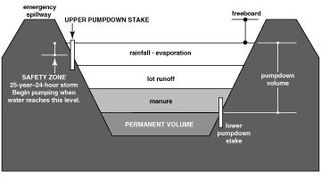
Cross section of a waste storage pond. Contributed to eXtension CC2.5
Irrigating with slurry calls for special equipment designed to handle both the high solids content and high fertilizer content of the waste.
Related Web Pages
- Liquid Manure Storage Treatment Options, Including Lagoons
- Role of Solid Liquid Separation in Manure Storage
- Earthen Manure Containment Structures
- Liquid Manure Treatment Lagoons
Recommended Reading About Manure Storage Ponds, Pits and Tanks
- Livestock and Poultry Environmental Stewardship Curriculum LPES Lesson 20: Planning and Evaluation of Manure Storage
- Livestock and Poultry Environmental Stewardship Curriculum LPES Lesson 24: Operation and Maintenance of Manure Storage Facilities
- American Society of Agricultural and Biological Engineers On-Line Technical Library, ASABE Technical Library EP393.3 Manure Storages
Research Summaries
- National Center for Manure and Animal Waste Management white paper summary, Closure of Earthen Manure Structures–Including Basins, Holding Ponds and Lagoons published by North Carolina State University. The full white paper can be ordered from MWPS, Iowa State University.
Page Managers: Ted Tyson, Auburn University, tysontw@auburn.edu and Saqib Mukhtar, Texas A&M University, mukhtar@tamu.edu .