Preferential Flow of Manure in Tile Drainage

Guidelines for Applying Liquid Animal Manure to Cropland with Subsurface and Surface Drains

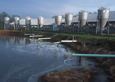
Liquid animal manure is a valuable source of nutrients and organic matter for crop production and may be applied by a variety of methods including spray irrigation,land surface spreading, and shallow subsurface injection. Because of relatively low nutrient concentration, liquid animal manure may be applied at relatively high volumes, but it is generally recommended that it not be applied at rates that exceed the soil infiltration rate, nor exceed the amount needed to bring the soil to field water holding capacity (Johnson and Eckert, 1995). Even when similar guidelines are followed, liquid manure discharges from agricultural drains has been reported in soils with subsurface drainage due to macropore flow (Geohring et al., 2001). | Related: Manure & Nutrient Management in Tile Drained Lands…

Figure 1. Liquid effluent contaminating surface water. (Photo courtesy of Rick Wilson, OEPA)

Application of liquid animal manures to soils with subsurface drainage has been linked to contamination of the effluent with nutrients (Cook and Baker, 2001; Geohring et al., 2001), particulate organic matter (Barkle et al., 1999), estrogens (Burnison et al., 2003), bacteria (Bicudo and Goyal, 2003; Cook and Baker, 2001; Dean and Foran, 1992; Jamieson et al., 2002; Joy et al., 1998),and antibiotics (Kay et al., 2004). These findings are not universal, however, as liquid animal manures can be applied without any detectable adverse effects on water quality. For instance, Randall et al. (2000) noted no difference in nitrogen, phosphorus, or fecal indicator bacteria losses in drainage effluent when comparing plots fertilized with liquid dairy manure and mineral fertilizer.

Check Out These Programs & Research About Tile Drainage

Swine Manure Timing & Subsurface Drainage

Tile Drainage Field Day

Use of Filters in Drainage Control Structures

New Technologies for Drainage Water Management

Role of Drainage Depth and Intensity on Nutrient Loss

The fact that liquid animal manure nutrients can be safely land recycled in some instances, but are discharged in subsurface drainage water under different circumstances, suggests a complex system that needs to be managed. Soil texture, available water holding capacity, tillage history, as well as the type and quantity of manure applied, application method, and timeliness of rainfall after application may all play a role in determining the fate of the manure.

Liquid Manure Applied to Subsurface-Drained Cropland

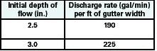
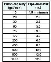
The available water holding capacity of the upper 8 inches of the soil provides an estimate of the maximum volume of water that can be applied before additional water, manure, and nutrients may begin to move through the soil profile (refer to Table 1). Manure application rates may need to be adjusted the day of application to avoid reaching the available water holding capacity of the soil and is one factor determining the maximum volume that should be applied. Application rates should not exceed the lower of the nutrient restriction, available holding capacity of the soil or 13,000 gallon/acre. Smaller multiple low applications allow the soil to absorb liquid animal manures better than one large application.

Table 1. Available Water Capacity (AWC) Practical Soil Moisture Interpretations for Various Soils Textures and Conditions to Determine Liquid Waste Volume Applications not to exceed AWC.

Suggestions To Minimize the Downward Movement of Liquid Manure

Have an Emergency Plan

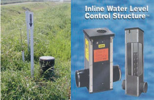
Identify subsurface drain outlets, and control or regulate discharge prior to application, or have on-site means of stopping the discharge from subsurface drains. Subsurface drainage outlets should be monitored before, during, and after application for potential liquid manure discharge. Drainage control structures and inline tile stops are recommended control practices to reduce the risk of a discharge, while tile plugs may be used in emergency situations but have been known to fail (Hoorman, 2004). Use caution not to back-up water where it may impair the functioning of an adjacent subsurface drainage system. Develop a contingency plan to handle situations when liquid manure discharges to ditches or streams.

Select Low-Risk Areas

Figure 2. Control structures and tile stops reduce surface water contamination if properly installed. (Image courtesy of Agri-Drain, Adair, IA)

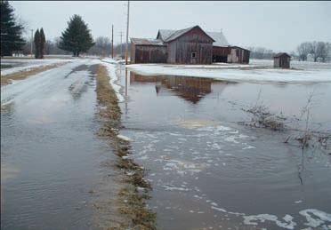
Liquid manure should not to be applied on soils that are prone to flooding, as defined by the National Cooperative Soil Survey (or in the Flooding Frequency Soil List posted in Section II eFOTG), during the period when flooding is expected. Manure can be applied if incorporated immediately or injected below the soil surface during periods when flooding is not expected.

Watch the Weather (Past and Future)

Avoid applying manure when rainfall is predicted, eminent, or directly after a rainfall event. After a significant rainfall event, the site should be allowed to drain to below field capacity, so that the soil has the capacity to absorb additional water or liquid animal manure. As part of the manure application record keeping, maintain a log of weather forecasts and actual weather conditions 24 hours before and after a manure application event.

Figure 3.Field prone to flooding. (Photo courtesy of Norm Widman, NRCS)

Keep Drains Well-Maintained

Repair broken drains and blowholes prior to application, and follow recommended/required minimum setback requirements (setback distances vary from state to state) for surface inlets. See fact sheet on Liquid Manure Application Rates for Subsurface and Surface Drained Cropland in “Related Publications” section.

Are Drains Flowing?

Figure 4. Avoid applying liquid animal wastes to saturated soils. (Photo courtesy of Rick Wilson, OEPA)

Liquid manure should not be applied to subsurface drained cropland if the drains are flowing. Generally, flowing subsurface drain indicate soil moisture levels that are near or exceeding the soil water holding capacity. The addition of liquid manure under these conditions will increase the probability of manure moving downward and discharging through these drains or moving overland as surface runoff.

Consider Concentration of Application

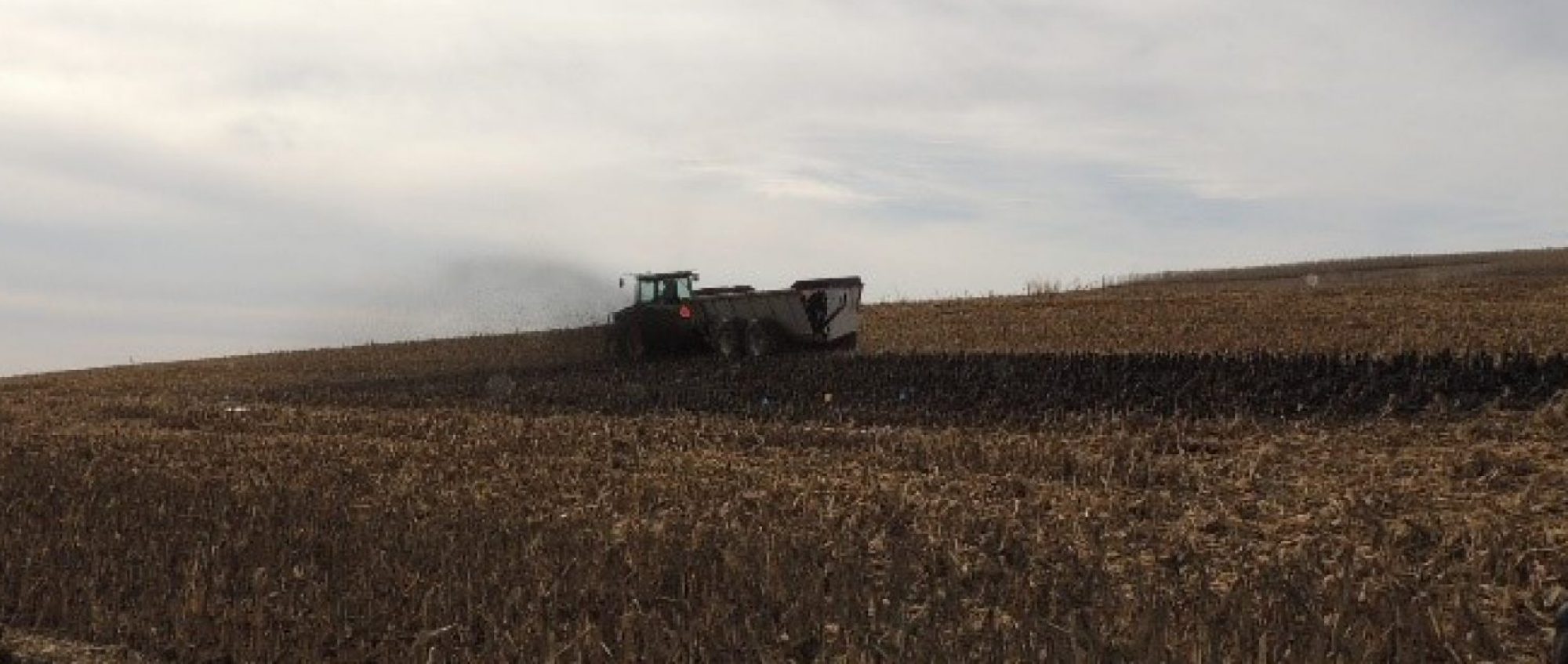
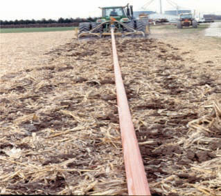
Application rates should be closely tied to nutrient requirements and available holding capacity of the soil. The method of application can influence application rates. For example, with an injection toolbar with four nozzles on 30-inch spacing, each knife and nozzle produces a concentrated application to a small area. Under these concentrated flow conditions, the effective rate differs considerably from an average application rate. The effective rate is calculated as the volume of manure applied per unit area per nozzle. For example, assume a 10,000 gallon/acre application rate, an injection toolbar with 30-inch spacing and 6-inch sweeps, the effective rate is 50,000 gallon/acre, five times greater than a uniform even distribution over an acre.

Avoid Ponding

Liquid manure should be applied in a manner that will not result in ponding, or runoff to adjacent property, drainage ditches, or surface water regardless of crop nutrient need; and should be uniformly applied at a known rate. Liquid animal manure applications using irrigation or surface application equipment tend to have a greater risk of ponding.

Consider Tillage

Fields with a history of downward movement of manure and/or bare/crusted soils may require some tillage to improve infiltration and absorption of the applied liquid. Prior to manure application, use shallow tillage to disrupt the continuity of worm holes, macropores and root channels (preferential pathways) to reduce the risk of manure reaching drain lines, or till the surface of the soil 3 to 5 inches deep to a condition that will enhance absorption of the volume of liquid manure being applied. This is especially important if shallow drains are present (< 2 feet deep). Any pre-application tillage should leave as much residue as possible on the soil surface to minimize soil erosion.

Clay Soil Considerations

Figure 5. A Paulding clay soil with high shrink swell capacity may need to be tilled before application, and/or smaller initial liquid applications to help close the cracks. (Photo courtesy of Jim Lopshire, The Ohio State University).

Clay soils with a high shrink swell capacity tend to have larger deeper cracks during dry conditions. These soils may require tillage to disrupt the cracks and macropores, and a lower initial application rate applied to the soil to help close the cracks. Cover crops may be planted to improve soil structure and absorb available manure nutrients. Determine the most limiting application rate based on the field conditions and nutrient limitations (may vary from state to state).

Depth of Injection

Figure 6. For the most effective application,liquid manure should be applied shallow and uniformly into the soil surface. (Photo courtesy of Jon Rausch, The Ohio State University).

Shallow injection is recommended for liquid manure. Till the soil at least three inches below the depth of injection prior to application, and/or control outflow from all drain outlets prior, during, and after manure application.

Perennial Crop and No-Till Precautions

For perennial crops (hay or pasture) or continuous no-till fields where tillage is not recommended, all subsurface drain outlets from the application area should be monitored, and if manure laden flow should occur, all effluent should be captured. Crops with deep tap root systems (alfalfa) tend to have more problems than hay crops with fibrous roots (grass) because liquid animal manures may flow along the tap roots to subsurface drains and outlet to surface water.

These criteria may be waived if the producer can verify there is no prior history of manure discharge via subsurface drains, or if a system is in place to capture the discharge. However, if there is a discharge, the producer is liable for damages and is subject to being classified as a Concentrated Animal Feeding Operation (CAFO).

Liquid Manure Applied to Systematic Surface Drained Fields

Fields or areas of fields that have systematic “surface drainage” systems e.g., shallow surface drains spaced 100 to 200 feet apart—NRCS Surface Drainage-Field Ditch Practice Standard 607) are considered concentrated flow areas. However, if special precautions are taken, manure can be applied in the surface drains with minimal risk of surface runoff. This does not apply to the collector surface drains (mains, ditches, etc.) or drains bordering the fields.

Figure 7. Till the soil 3 to 5 inches deep or 3 inches below the depth of injection to disrupt macropores. (Photo courtesy of Jon Rausch, The Ohio State University).

The following special manure application techniques shall be used:

  1. Till the soil surface at least 3 to 5 inches deep prior to liquid manure surface application. Pre-till within 7 days of application.
  2. Surface-apply liquid manure uniformly over the entire soil surface on the freshly tilled soil (3 to 5 inches) to allow the liquid manure to be absorbed into the soil surface.
  3. For fields with no subsurface drainage, liquid manure can be injected directly without prior tillage. If subsurface drainage is present as well as surface drains, then the above recommendations for subsurface drained cropland apply as well.

d. Manure application rates should be adjusted to consider the most limiting factor and include the ability of the soil to accept, store and hold liquid manure, water, and nutrients.

Follow recommended/required setbacks from environmentally sensitive areas for surface inlets. See fact sheet on Liquid Manure Application Rates for Subsurface and Surface Drained Cropland.

Summary

Improved management is a key issue in greatly reducing the potential of liquid manure reaching our surface water. While climate and some environmental conditions cannot be controlled, producers can better manage and control when and how they apply liquid manure. These recommended practices are intended to help producers apply liquid manure in a manner that minimizes the potential to impact water resources through the downward movement of manure into subsurface (tile) drains. These recommendations incorporate the best available knowledge.

Acknowledgments

The authors acknowledge Dr. Harold Keener, The Ohio State University; Dr. Timothy H. Harrigan and Dr. William G. Bickert, Michigan State University; Michael J. Monnin and Frank E. Gibbs, Ohio Natural Resources Conservation Service, and Susanne R. Reamer and Michael I. Gangwar, Michigan Natural Resources Conservation Service, team members who helped organize and conduct the “Liquid Animal Manure Application on Drained Cropland: Preferential Flow Issues and Concerns Workshop” and reviewed the regional guidelines. The workshop was organized and sponsored by The Ohio State University, Michigan State University, and cooperating organizations, with partial support from the USDA–CSREES Great Lakes Regional Water Quality Program, USDA–Natural Resources Conservation Service, Ohio Compost and Manure Management, Ohio State University Extension, Great Lakes Basin: Soil Erosion and Sediment Control, and the Overholt Drainage Education and Research Program.

References

  • Barkle, G.F., T.N. Brown, and D.J. Painter. 1999. Leaching of particulate organic carbon from land-applied dairy farm effluent. Soil Science 164 (4): 252–263.
  • Bicudo, J.R., and S.M. Goyal. 2003. Pathogens and manure management systems: A review. Environmental Technology 24 (1): 115–130.
  • Burnison, B.K., A. Hartmann, A. Lister, M.R. Servos, T. Ternes, and G. Van Der Kraak. 2003. A toxicity identification evaluation approach to studying strogenic substances in hog manure and agricultural runoff. Environmental Toxicology and Chemistry 22 (10): 2243–2250.
  • Cook, M.J., and J.L. Baker. 2001. Bacteria and nutrient transport to tile lines shortly after application of large volumes of liquid swine manure. Transactions of the American Society of Agricultural Engineers 44 (3):495–503.
  • Dean, D.M., and M.E. Foran. 1992. The effect of farm liquid waste application on tile drainage. Journal of Soil and Water Conservation 47 (5): 368–369. *Geohring, L.D., O.V. McHugh, M.T. Walter, T.S. Steenhuis, M.S. Akhtar, and M.F. Walter. 2001. Phosphorus transport into subsurface drains by macropores after manure applications: Implications for best manure management practices. Soil Science 166 (12):
  • Hoorman, J.J. 2004. Ohio liquid manure violation water quality data, Ohio Journal of Science, Vol. 104, No. 1, A-34.
  • Hoorman, J.J., J.N. Rausch, T.M. Harrigan, W.G. Bickert, M.J. Shipitalo, J.R. Reamer, F.E. Gibbs, M.J. Gangwar, and L.C. Brown. 2005. Summary of education and research priorities for liquid manure application to drained cropland: preferential flow issues and concerns, ASAE Meeting, Paper No: 52062. Tampa Bay, FL.
  • Jamieson, R.C., R.J. Gordon, K.E. Sharples, G.W. Stratton, and A. Madani. 2002. Movement and persistence of fecal bacteria in agricultural soils and subsurface drainage water: A review. Canadian Biosystems Engineering 44: 1.1–1.9.
  • Johnson, J., and D. Eckert. 1995. Best management practices: Land application of animal manure. Ohio State University Extension Publication AGF-208-95 Available online at http://ohioline.osu.edu/agf-fact/0208.html (Verified 8 September 2004).
  • Joy, D.M., H. Lee, C.M. Reaume, H.R. Whiteley, and S. Zelin. 1998. Microbial contamination of subsurface tile drainage water from field applications of liquid manure. Canadian Agricultural Engineering 40 (3):153–160.
  • Kay, P., P.A. Blackwell, and A.B.A. Boxall. 2004. Fate of veterinary antibiotics in a macroporous tile drained clay soil. Environmental Toxicology and Chemistry 23 (5): 1136–1144.
  • Randall, G.W., T.K. Iragavarapu, and M.A. Schmitt. 2000. Nutrient losses in subsurface drainage water from dairy manure and urea applied for corn. Journal of Environmental Quality 29 (4): 1244–1252.
  • Rausch, J.N., J.J. Hoorman, T.M. Harrigan, W.G. Bickert, M.J. Shipitalo, J.R. Reamer, F.E. Gibbs, M.J. Gangwar, and L.C. Brown. 2005. Guidelines for liquid manure application on drained cropland, ASAE Meeting, Paper No: 52061. Tampa Bay, FL.

Related Publications

Recirculation Systems for Manure Removal

Recirculation Systems for Manure Removal in Hog Confinements

Originally published as PIH-63.

Authors: Don D. Jones, Purdue University; Eldridge Collins, Jr., Virginia Tech

Reviewers: Doug Hamilton, Oklahoma State University; Jay Harmon, Iowa State University


Figure 1

Recirculation systems involve the addition of varying amounts of dilution water in order to improve the removal of manure from the animal area. The two types of recirculation systems used in pork production facilities are underslat flushing and pit recharge systems. Both systems use a shallow gutter that is flushed or drained periodically to remove waste from the building to the lagoon or storage basin. Open gutter systems have been used in the past but are no longer recommended because of concerns with disease transmission.

A flush system operates by using a surge of water to flush manure from the gutter. Water is periodically released into the gutter, usually with a flush tank (Figure 1). The amount of flush water and the flush frequency are designed to provide enough water to ‘scour’ manure from the gutter. Large volume pumps are sometimes used to provide flush water instead of flush tanks and smaller pumps. Spent flush water and manure enter the lagoon where it is treated and later reused for flushing. In areas where irrigation is practiced, fresh water may be used for flushing instead of recycled water and the flushed wastewater can be stored for later land application.

Pit recharge involves the periodic (three days to three weeks) draining of the pit contents by gravity to a lagoon/ basin, then recharging the pit with about 12 inches of new liquid in a short time, usually less than four hours. Regular pit draining removes much of the manure solids that would otherwise settle and remain in the bottom of the pit. Liquification of settled solids increases their likelihood of removal at the next pit draining. With less organic matter available for bacterial digestion, there is less gas production in the dilute pit contents, and a better in-house environment. In addition, fewer odorous gases are exhausted from the pits to the surrounding building vicinity. Regular and frequent loadings of manure also enhance lagoon performance. In farrowing and nursery buildings, pits typically are drained and refilled between groups. During winter months, cleanup water may be used as refill water to minimize radiant heat loss from the small pigs to cold recycled lagoon or basin water.

Advantages and Disadvantages

Recirculation systems have the greatest appeal to operators who wish to store manure outside the building and to those with suitable locations for lagoon or earthen basin construction, since the additional dilution water requires an earthen storage in order to economically handle the larger volume of manure. Assuming that the hog operation can accommodate a recirculation system, what are its advantages and disadvantages?

Advantages

  • Reduces in-house gases and odors. Frequent removal of the manure significantly reduces the characteristic ‘clinging’ odor inside the building and improves air quality. A three year study in North Carolina demonstrated that pit recharge systems have lower ammonia levels than either underslat flush or deep pit systems.
  • Adapts to building conversion. Older buildings are more easily converted to shallow recirculation gutters than deep pits since less construction is required.
  • Requires less land for manure application since up to 80% of the fertilizer nutrients are lost in the lagoon. (It should be noted that the P and K are concentrated in the lagoon sludge and may eventually be land applied.)

Disadvantages

  • Greater nutrient loss. Lagoon-treated animal manure has a greater nutrient loss than manure stored under a slotted floor.
  • Requires a relatively large land area for a lagoon. A lagoon takes four to six times more land area than the building itself.
  • Subject to mechanical problems. A recirculation system has mechanical components such as flush tanks and pumps that are subject to breakdown.
  • Lagoons/basins are a potential odor source if not designed and operated properly. They are not suitable in some locations, due to prolonged cold weather or proximity to neighboring residences.
  • Flushing may increase humidity in cold weather.

Basic Parts of a Recirculation System: Design and Operation – Pit Recharge System

A pipe from the main recharge line is installed into each pit, preferably as far as possible from the drain outlet. However, the location of this recharge pipe is not critical since liquid addition to the pit is the objective rather than a high velocity scouring action for flushing. The inlet pipe can be either stubbed directly into the pit wall with a conveniently located and protected butterfly valve outside the building, or it can enter the building wall near ceiling level and drop down to the pit with an inside-thebuilding valve. The diameter should not be reduced between mainline and pipe discharge.

The recharge system can be managed successfully with a flat pit floor, although a minimum slope of 1 inch in 20 feet to the drain is recommended to overcome uneven concrete construction. Enough pit depth must exist to cover the upper end of the pit floor with at least 6 inches of liquid while leaving at least 12 inches between the slats and the liquid at the highest part of the pit floor.

Underslat Flush Gutter Design

At least one-third of the floor area should be slotted. Manure removal from a flushed underslat gutter depends on the velocity, depth, duration, and frequency of the flush. These factors are determined by the dimensions and slope of the gutter and by the rate flush water is added to the gutter. To adequately clean the gutter, a flush velocity of at least 2.5ft per second is needed. A minimum of a 2.5in. depth of flow with at least a 10-second flush is recommended. For channels longer than 150ft or with flushing devices which have a longer flush duration, such as siphons, increase the flush volume proportionally to provide the needed cleaning action. A rule of thumb is to increase the initial depth of flow by 50%, or 0.5in. for each 25ft of gutter length beyond 150ft.

The flush device determines the initial depth of water flow. For instance, a 3in. siphon provides water for only about a 1in. depth of flow in a 24in. wide gutter, whereas larger siphons provide greater depths and can flush wider gutters. Since 3in. and 4in. diameter siphons release water in about 30 seconds, flush volume must be increased to compensate for the lower flowrate. A ‘tipping bucket’ flush tank can deliver a 3in. depth of flow in almost any width gutter with a 5-10 second release, while the door opening and volume of a ‘trap door’ tank can be designed to provide almost any depth of flow and flush duration.


Table 1


Figure 2

Consider depth of flow in selecting the gutter slope. Table 1 presents the recommended slopes for flushed gutters with various initial flow depths. To achieve the same cleaning action with less gutter slope, a greater depth of flow is required.

Slightly crown (1/4in.) the gutter floor and give a smooth finish. Gutters wider than 4ft should be subdivided into widths of 1.5-2 ft except for the first 10-20ft to allow the flush water to evenly distribute across the gutter width. This keeps water from channeling around waste deposits as it moves down the gutter. Inverted concrete hog slats or 6in. vinyl strips or 1×6 P.T. plank embedded in the floor work well for this purpose (Figure 2). For gutters longer than 200ft, consider draining both ends toward the middle of the building, and consult a knowledgeable building engineer for assistance.

Wherever possible, use gravity to carry waste to the lagoon or manure storage basin. Generally, a sewer line 8in. in diameter with a 0.5% slope is sufficient to carry manure to the lagoon. For flush tanks larger than 1000gal or where the same sewer line must handle several flush tanks, contact a knowledgeable engineer to determine if a larger sewer line or additional slope is needed. Locate a sump pit to collect discharged (or runoff) flushed wastewater. The drain line to the lagoon should be designed to prevent manure gases from the storage and drafts from entering the animal area.

Flush Equipment Design – Flush Frequency

Table 2


Table 3


Table 4

The required frequency of flushing is determined by two factors: animal density and the solids-carrying capacity of the water. The minimum flushing frequency can be determined by dividing the total daily flush volume (Table 2) by the recommended flush volume (determined by channel geometry in Table 3). Typical flush frequencies are twice a day for farrowing, nursery, and gestation buildings to four times a day for finishing buildings. When underslat gutters are flushed manually, the volume per flush is determined by simply dividing the flush volume per day by the number of flushes per day. Odors from underslat floors can be lessened by flushing at least four times a day, although pit ventilation in addition to frequent flushing is needed for best control of ammonia odors.

To insure cleaner pens in partially slotted buildings, keep hog density at about 4ft2 per 100lb of animalweight, use solid partitions except at the gutter area to help establish the desired dunging patterns, and adjust the ventilation system to keep the slat area colder than the resting area. Producers may need to floor-feed pigs during their first week in the building to help establish good dunging habits on partially slotted floors. A 1.5in. stepdown to the slats from the solid area also helps establish desired dunging habits.

Flush Devices

Figure 3


Several types of flush devices have been developed to provide the required flush volumes: automatic siphon tanks, tipping buckets, trap door tanks, manual dump tanks, and large volume pumps.

Automatic siphon tank: This tank has the singular advantage of no moving parts (Figure 3). As the tank slowly fills with water, an air bubble trapped under the bell is forced out a siphon pipe until it triggers the siphoning action. An automatic siphon tank can be placed above the pens to reduce tank floor space requirements.

Commercially available 8-24in. diameter automatic siphons can handle very large volumes of water. These flush units typically use a 1-1/2in. airrelease pipe to trigger the large siphon. Large siphons are well suited to flushing underslat gutters.

Figure 4

Tipping tank: A tipping tank dumps when it fills to a depth where the center of gravity of the water volume over-balances the pivot point. Usually the tank is elevated 4-6ft off the floor and the water is dumped backwards onto a curved spillway. This increases the velocity and lowers the head of water so it will clear a 9-10-inch opening between the bottom of the first slat and the surface of the gutter. Because the water discharges all at once, flushing velocity and depth are high and can cover a gutter 8-10ft wide (Figure 4). Gutters flushed with a tipping tank should be 12 inches deep or more to minimize water splash into the first pen.

Trap door tank: This flush tank has more moving parts than either of the above but allows greater design flexibility because both tank volume and trap door can be modified to meet individual needs. Care and precision are necessary to get a watertight seal around the door. An automated version of the trap-door or hinged-gate valved tank gives the flexibility of more frequent flushings when the operator is not present. The valve consists of a float-controlled flat plate that sets against a section of the PVC pipe in the tank bottom.

Large volume pumps: Large volume pumps can be used for flushing if sized to provide at least 100gpm per ft of gutter width, about 1-1/2in. water depth. The pump should operate 4-5min per flush channel at least two times a day for adequate flushing. Since additional cleaning is possible by operating the pump for a longer period, depth of flow does not need to be as great as with flush tank and flow dividers become more important to make sure distribution of water front is accomplished in wide gutters.

Waste Treatment Lagoons

Figure 5

A properly designed and operated lagoon is essential to the success of a flushing system (Figure 5). Although a single stage lagoon can operate satisfactorily in an underslat flushing system, a two-stage lagoon is preferred to minimize odor and potential disease transmission.

The design criteria for lagoons used with recirculation systems are the same as for conventional swine manure lagoons. See PIH-62, “Lagoon Systems for Swine Waste Treatment,” or MWPS-18, “Livestock Waste Facilities,” available from Midwest Plan Service, for design information on lagoons in your area.

Pumps and Pipes

In recirculation systems, pumps or gravity transport effluent from the lagoon to the building. In some cases, pumps are also needed at the low end of the gutter to transport wastewater to the lagoon.

Lagoon-to-Building Pump

Figure 6


Figure 7

In pit recharge, a low-pressure, self-priming centrifugal or submersible pump with enough flow capacity to recharge the largest building pit with an average of 12 inches of liquid in 4 hours or less is normally recommended. The pump intake is generally an open-ended suction pipe floating approximately 18 inches beneath the liquid surface of the lagoon. It may be screened with a 1 inch wire mesh fence or a basket with a total opening that is at least five times the opening area to the suction pipe.

Slow speed pumps (1725rpm or less) cost more initially but usually last longer than higher speed pumps (3450rpm). Because of their shorter service life, it is a good idea to keep a replacement recharge pump on hand. Minimize the use of metal parts in contact with recycled lagoon water to prevent salt deposition that can plug the line. A lagoon-to-building pump can be placed on the lagoon bank in an insulated enclosure or in a wet-well sunk in the bank (Figures 6 and 7). The pump must be protected from freezing weather.

The intake pipe from the lagoon to the wet-well should be at least 18 in. below the lagoon surface, several feet from the bank and as far away as practical from the point where the waste enters the lagoon. Locate the pump as close as practical to the high water level of the lagoon (preferably below the low water level using a flooded suction) to minimize pump priming problems. The pipe must be installed within the berm during lagoon design and construction using anti-seep collars and proper engineering design.

Flush Gutter-to-Lagoon Pump

If a pump is needed to lift effluent from the building to lagoon, it should be a commercial grade, sewage lift-type activated with a float switch. Pump capacity should be determined in relation to the size of the sump that collects the spent wastewater to adequately handle the highest flow rate resulting from the flush tank discharges. Pump intake should have an adequate cleanable screen area.

Piping

Table 5

The pipe from the lagoon pump to the gutter can be relatively inexpensive plastic pipe and, if possible, should be one continuous piece. See Table 5 to determine the size you will need. Note the earlier warning about installing the pipe through the berm.

Salt Deposition Problems

If water is recycled from the treatment lagoon, salt buildup in pumps and pipes is a common problem. Avoid sharp turns in the supply pipe because they add to pressure drop and create turbulence conducive to salt precipitation. Regular addition of dilution water to the lagoon and removal of salts by irrigation will reduce problems. In most areas of the U.S., add a volume of dilution water that is equal to the volume of waste added. Use fresh water, lot runoff, roof runoff, or other sources for dilution water.

Dilute acetic or hydrochloric (muriatic) acids can be used to dissolve salt deposits. Muriatic acid can be bought in paint and hardware stores and is usually available at 20% solution. Plastic pipe can be dosed with undiluted 20% muriatic acid solution by filling the piping system with this acid, letting it stand overnight and then flushing the acid solution through the system. If possible, field spread this acidic high salt material at a very low rate, rather than back to the lagoon. If the flush system has metallic parts such as pump housing or metal valves, the acid should be diluted (1 part acid to 12 parts water) to prevent damage to the metal. CAUTION: DO NOT ADD WATER TO CONCENTRATED ACID! WHEN MAKING THE DILUTION- ALWAYS ADD THE CONCENTRATED ACID TO WATER. Use care and wear protective equipment because mixing acid can be very dangerous!

The following recommendations can reduce the rate of salt buildup on a recycling system:

  • Ground the electric pump-housing to prevent an electrostatic charge from building up on the metallic pump by attaching a cable to the pump-housing and to a ground rod driven into damp soil.
  • The pump suction line must be large enough to prevent cavitation (excess turbulence, resulting in a sharp pressure drop and increased salt deposition). A rule of thumb is that the suction line should be one standard size larger than the discharge of the pump. Locate the pump below or as close to the lagoon water level as possible to minimize the suction lift.
  • If the pump does not run continuously, modify the system so the pipes can drain between use.
  • The pipe from the lagoon to the gutter should have a minimum diameter of 1-1/2 in. The problems are not as great in larger lines as they are in smaller ones. (See Table 5).
  • Consider oversizing the supply pump and piping system, operating it on a timer, and allowing the system to drain when not in use. While more expensive to purchase, contact time between the pump and pipes and the lagoon water can be greatly minimized in this manner.


Table 1. Recommended slope for flushed gutters.

Table 2. Minimum required volume of flush water/day.

Table 3. Minimum gallons of water required to flush gutters at various depths of flow (5-10 second release).

Table 4. Tank discharge rates required to flush gutters at various depths of flow.

Table 5. Recommended pressure pipe sizes for various flow rates (Max. flow velocity=2.5fps)/

1. Determine dimensions of gutters. a) Gutter width b) Initial depth of flow (table 1 has recommendations) c) Gutter slope (table 1) 18ft 2.5in 1.5%

2. Determine flush volume and tank capacity. a) Required daily flush volume 720 hogs x gal of flush water/head/day (table 2) b) Minimum flush volume/gutter (table 3). If gutter is longer than 150ft, in¬crease flush volume by 50%. Total flush volume: gutter width x 45 gal/ft c) Volume/flush required if each gutter is flushed 6x a day. (Actual must be greater of 2.b or this volume) (Step 2a) ÷ (2 gutters x 6 flushes/day: 10,800 gal 1,215 gal 14,580 gal/day

3. Determine size of return pump from lagoon to flush tank. a) pump capacity to supply required flush volume (Step 2.d) ÷ 1,440 min/day b) Actual minutes between flushes (assume 12gpm pump is available and fills both tanks equally). (Step 2c) ÷ 12 gal/min 10.125 gpm 202.5 min

4. Determine size of return pipe (lagoon to flush tanks).* a) Select from table 5 using flow rate for pump selected in step 3. 2 in.

Pit Recharge Option Calculations

1. Determmine drop in gutter floor due to slope. Assume gutter slopes 1in/20ft. 1/20 x 160ft: 8 in. 2. Gutter width (18ft wide with dividers 2ft o.c.) 18 ft. 3. Gutter recharge depth at high end: minimum depth 6in 12 in. 4. Gutter volume if floor were level (length x width x depth at high end) (Step 3). 160ft x 18ft x 1ft: 2,880 cu ft 5. Gutter volume due to sloping floor: 1/2 x drop (Step 1) x length x width: 1/2 x 8in x1ft/12in x 160ft x 18ft: 960 cu ft. 6. Total recharge volume: Step 4 + Step 5 3,840 cu ft. 7. Total recharge volume in gallons Step 6 x 7.5 gal/cu ft: 28,800 gal 8. Recycle pump capacity needed to charge pit in 4hr: Step 7 ÷ (4hr x 60min/hr): 120 gal/min

  • Consider a larger pump and piping system and operating with a timer and float to minimize contact with corrosive lagoon water and salt deposition. A good rule of thumb is to operate the pump no more than 2 hours/day total.

Figure 1. Perspective showing the components of a flush gutter system.

Figure 2. Cross section of an underslat flushed gutter with dividers.

Figure 3. An elevated automatic siphon tank being used in a farrowing house.

Figure 4. Tipping bucket tank used for flushing underslat gutters.

Figure 5. Cut-and-fill construction for two-stage swine waste lagoon system.

Figure 6. Diagram of a wet-well configuration.

Figure 7. Pumping for a lagoon using a wet-wall and dry-wall configuration.

Horse Manure Management

With proper planning, manure management can be beneficial to both the farm and the environment. This article provides information on environmental and health impacts of manure as well as proper manure storage and management.

J.G. Davis, A. M. Swinker, and Crystal Smith

Introduction

Manure management is a vital part of modern day horse ownership. Many horses spend a significant portion of their day in stalls, accumulating large amounts of manure and stall waste. Horse owners generally have a limited amount of time to spend caring for their equine charges; thus, efficient manure removal and disposal is crucial. Additionally, horse facilities are often managed on relatively small acreage, limiting manure storage and application options.

The intent of this publication is to educate horse owners on the effective management of horse manure. Horse owners will first gain a thorough understanding of the quantity and characteristics of manure produced by horses. Finally, on-site options for handling, storing and treating manure will be discussed, keeping in mind sound facility management and environmental stewardship.

Managing horse manure can be a complex topic, and the principles presented here should be tailored to your specific situation. Please contact your local extension agent or natural resources conservation service field office for technical support.


Horse Manure Production and Characteristics

Person cleaning horse stall

Horses produce large amounts of manure. In fact, if the manure produced from one horse were allowed to pile up in a 12-foot-by-12-foot box stall for one year, it would accumulate to a height of 6 feet. On any given day, the average 1,000-pound horse will produce approximately 50 pounds of manure. This amounts to about 8.5 tons per year.

Manure is not the only material being removed when stalls are cleaned. Wet and soiled bedding material must also be removed and can equal almost twice the volume of the manure itself. The amount of bedding material removed will vary by type — shavings, sawdust, straw — but on average, totals between 8 and 15 pounds. Total stall waste produced averages between 60 and 70 pounds per day, which amounts to approximately 12 tons of stall waste per year.

When managed properly, horse manure can be a valuable resource. Manure is a source of nutrients for pasture production and can be utilized as part of a pasture management strategy to improve soil quality. The fertilizer value of the 8.5 tons of manure produced annually from a 1,000-pound horse can amount to 102 pounds of nitrogen (N), 43 pounds of phosphorous (P2O5) and 77 pounds of potash (K2O). Nutrient values for manure vary widely. The type and quantity of bedding material included also affects the overall fertilizer value. If a more accurate measure of nutrient content is needed, contact your local cooperative extension office for a list of laboratories that perform manure analysis.

Environmental and Health Impacts

Many horse owners do not have enough land or vegetative cover to properly apply large amounts of manure and nutrients. If not managed properly, manure can deposit excess nutrients into the environment via surface runoff or as a leachate, or water-contaminated with manure, from improper manure storage and land application. This can negatively impact water quality and subject landowners to investigation, and in some cases, legal action under an Agricultural Stewardship Act. For these reasons, horse operations are encouraged to use best management practices and develop a nutrient management plan. Nutrient management plans describe the farm’s manure production, soil fertility and recommended manure application and removal rates. For more information on designing a plan specific to your farm’s needs or identifying other conservation resources, contact your local cooperative extension office.

Internal parasites, insects, rodents and odors can be manure-related health concerns on horse farms. These issues can be minimized through carefully planned manure storage and handling. Internal parasites may be found in horse manure and can compromise the health and welfare of the horses stabled or grazing the land. Composting manure and properly timed land application can limit the risk of parasite exposure. Insects, especially flies, become a nuisance on farms where stockpiled manure serves as fly larvae habitat. Flies breed when spring temperatures rise above 65-degrees F. Flies deposit their eggs in the top few inches of moist manure, and these eggs can hatch in as little as seven days under optimal temperature and moisture conditions. Therefore, fewer flies will develop if you remove manure from the site or make it undesirable for fly breeding through processes such as composting within a maximum seven-day cycle. Naturally occurring fly predators can also be used to limit the fly population at the manure pile but are no replacement for sound management practices. Rodents can be a problem when manure is stockpiled for extended periods of time, providing them with a warm, safe environment. Additionally, nuisance odor from manure piles can result in strained relationships with neighbors. Composting or timely removal of manure piles will help keep odors to a minimum. Finally, keep in mind that large piles of manure are not aesthetically pleasing to your neighbors or those visiting your farm. Keeping the manure storage site screened with vegetation or fencing or by location will help to enhance the beauty of your farm.

Horse Manure Storage and Utilization

The average horse produces between 60 and 70 pounds of stall waste per day. Multiply this by several horses, and it is easy to see the importance of having methods in place to manage the manure produced on a daily basis. Letting manure pile up in stalls and paddock areas leads to a host of problems. It is not only unhealthy for your horse — inviting for pests and odors — and aesthetically unpleasing, but the sheer amount of manure produced will overwhelm you. Many handling and storage options exist, but it’s up to you to choose the method that best suits your horse operation.

Horse operations with available land may choose to apply stall waste to pastures as fertilizer. This should be done based on soil-test results and nutrient needs. A soil analysis is needed to determine the fertility needs of a pasture. Soil analysis is provided through your land-grant university’s soil testing laboratory for agricultural operations, which include horse farms, free of charge. Contact your local cooperative extension office for instructions on how to take a soil sample. There are also private laboratories that offer soil-testing services.

In many situations, manure can be picked directly from the stall, deposited into a manure spreader, applied to the pasture and harrowed into the soil. Barns not constructed with a management scheme allowing for stall access by a manure spreader require manure to be carted from the stall to the manure spreader some distance away. In this case, ramps or dropped spreader parking can be helpful to avoid lifting the heavy, cumbersome stall waste. Keep in mind that when spreading manure from stalls bedded with sawdust or shavings, the applied stall waste can stunt plant growth. Wood products contain carbon that soil microbes use for energy but not enough nitrogen to build proteins. The microbes draw nitrogen from the soil to make up for this deficit to such a degree that they can actually limit plant growth. To manage this nitrogen deficiency, nitrogen fertilizer can be applied. Or, to avoid the problem completely, manure can be composted before it is applied to the land.

When direct pasture application is not an option, manure storage facilities become a necessity. The storage facility should be convenient to the barn. A general rule of thumb is to plan for 180 days of long-term manure storage. This allows operations the flexibility to store manure when conditions are not ideal for manure application, as when fields are frozen or wet. This storage area should be accessible to the equipment that will ultimately remove the accumulated stall waste. Manure storage facilities should also be downwind and screened from nearby homes to avoid potential complaints about odors and aesthetics. The size, type and location of manure storage facilities will vary by horse operation based on the amount of manure produced, length of time the manure will be stored and available land area. Always be sure to contact your local authorities regarding zoning regulations and additional restrictions.

Minimum separation distances commonly recommended for composting and manure-handling activities. Source: On-Farm Composting Handbook, NRAES-54
Sensitive Area Minimum Seperation Distance (feet)
Property Line 50-100
Residence or place of business 200-500
Private well or other potable water source 100-200
Wetlands or surface water (streams, ponds, lakes) 100-200
Subsurface drainage pipe or drainage ditch discharging to a natural water source 25
Water Table (seasonal high) 2-5
Bedrock 2-5

Manure Storage Construction

Manure storage should be designed to limit the chance of leachate entering surface and groundwater resources. Ideally, storage piles should be placed on gravel, hardened clay or concrete pads that slope inward. The construction of manure storage sites will vary, based on individual situations and soil types. For instance, concrete pads may be necessary in areas with sandy soils where contaminants are more likely to reach groundwater. Storage piles should not be placed in low-lying or flood-prone areas, and care should be taken to direct water from higher elevations away from the site. The natural resources conservation service or local soil and water conservation district offices can provide individualized manure storage design specifications.


Composting

Composting horse manure is relatively simple but does involve more than simply piling the water. While many farms stockpile their manure, few truly compost. Composting is essentially managed decomposition. Managing the process can virtually eliminate odor, flies, weed seeds and internal parasites found in horse manure and create a valuable soil amendment for resale or for pasture application. To manage a compost pile, the following factors must be taken into consideration: carbon to nitrogen ratio, oxygen, moisture and temperature.

Compost Pile

The microorganisms found in compost are most active when their diet contains about 30 times more carbon than nitrogen, or a C:N ratio of 30:10. Horse manure’s C:N ratio is typically 40:1 due to the large amounts of bedding mixed with it but generally doesn’t require additional nitrogen provided it has enough moisture and oxygen.

Composting is an aerobic process, that is, it requires oxygen. If a compost pile doesn’t get enough oxygen, these anaerobic conditions can result in unpleasant odors, such as those normally associated with stockpiling manure, and slowed decomposition. There are several ways to provide oxygen to a compost pile. The most common way is to turn the pile. For large piles or windrows, turning is generally done using the bucket of a tractor or front-end loader. For smaller piles, a pitchfork will certainly get the job done; but for these operations, you may want to consider using an aerated, static-pile design, which doesn’t require turning.

Typical horse-stall waste tends to be dry and will need added moisture to create the ideal conditions for compost microbes. The moisture content should be about 50 percent, or roughly the consistency of a wrung-out sponge. If rainfall does not provide enough additional moisture, the pile may need to be watered periodically. On the other hand, too much water can also be detrimental, displacing oxygen inside the pile and causing anaerobic conditions. If environmental conditions such as rain or snow are providing too much water, the pile may need to be covered. Some compost-storage designs call for permanent roofs, but properly anchored plastic tarps can be just as effective.

Compost Trouble Shooting
Problem Possible Cause Remedy
Fresh manure, but pile won’t heat up. The pile is: 1) too dry,
2) too wet; and/or
3) Outside temp is too cold.
1) Add water evenly to pile.
2) Aerate and cover.
3) Wait for warmer temps and turn as needed.
Pile was hot, but now temps are falling. 1) Pile is settling.
2) Moisture is less than 50 percent.
1) Turn pile; and/or
2) Add water evenly to pile.
Pile is more than 160-degrees F and has gray ash-like mold. Pile is too dry. Add water evenly to pile.
Pile has gone through two or more heat cycles but still has some material that has not decomposed. Wood shavings decompose slowly. Ensure pile has proper moisture content, add water if needed.
Pile emits bad odor. Pile is too wet and has become anaerobic inside. Turn to aerate and increase water evaporation, apply cover to limit additional rainwater.

* Table does not include all scenarios, see resources/references for more in-depth publications on the subject.

One of the best ways to monitor your compost pile is by using a thermometer. Compost thermometers should have a probe at least 36 inches long and are available through many garden supply stores. The goal is to have sustained temperatures of 130- to 150-degrees F in the pile interior. This will optimize decomposition and also kill pathogens and weeds.

Compost-pile design and storage facilities will depend on the size of the operation and the equipment available. For a farm with two to six horses, small static piles, which use perforated PVC pipes to draw in air and don’t require turning, may be ideal. While not necessary, the use of multiple bins can allow separation of distinct batches. In this situation, horse manure should be piled approximately 5 to 8 feet high with a base that is two times the width and length of the height. For example, a 10-foot by 10-foot bin could accommodate a pile that is 5 feet high. PVC pipes should be placed after the pile is about 1 foot high so that the ends remain visible as more manure is added.


Aerated Static Pile with perforated PVC pipes Example of bins suitable for small farms - doors and roof are optional


For larger farms with access to bucket loaders, manure spreaders and/or specialized composting equipment, larger piles or windrows may be the most efficient design options. These piles may be slightly larger in height and width and considerably longer but will require periodic tuning.

Example of mixing / storage area with buckwall


Compost will decompose more efficiently if the mix is uniform. Starting with a uniform mix is even more important in the case of static piles, since they will not be turned during the decomposition process. Some farms utilize a temporary storage and mixing area to aid in this process.


Benefits of Composting

  • Creates valuable soil amendment
  • Stabilizes nitrogen into a slow release form
  • Avoids the problem of nitrogen immobilization
  • Reduces manure volume by 50 percent
  • Destroys weed seeds, fly larvae and internal parasites
  • Eliminates or reduces the cost of off-site disposal


Conclusion

With careful planning, proper manure management not only protects the environment and increases the efficiency and aesthetics of your farm, but might also save you money while enhancing your pastures. The following resources provide more information on composting and additional facility design specifications.

Field Guide to On-Farm Composting and the On-Farm Composting Handbook, available from the Natural Resource, Agriculture, and Engineering Service(NRAES) at www.NRAES.org.

Horse Facilities Handbook, available from the MidWest Plan Service at www.mwpshq.org.

Check out your local university’s agronomy handbook containing information on soil production, soil sampling, nutrient management, utilization of organic waste and more.

A Review of Manure Injection to Control Odor and Ammonia Emissions During the Land Application of Manure Slurries

Reprinted, with permission, from the proceedings of: Mitigating Air Emissions From Animal Feeding Operations Conference.

The proceedings, “Mitigating Air Emissions from Animal Feeding Operations”, with expanded versions of these summaries can be purchased through the Midwest Plan Service.

This Technology is Applicable To:

Species: Swine, Dairy, Beef
Use Area: Land Application
Technology Category: Management (manure injection/incorporation)
Air Mitigated Pollutants: Odor, Ammonia

System Summary

Manure slurry injection provides a significant reduction in land application odor and ammonia emissions release when compared to conventional manure surface broadcasting. Release of odor and ammonia during land application can be reduced by more than 90% compared to conventional application methods (Ohio State University, 2007). Manure can be successfully injected in both conventional tillage and no-till systems with currently available equipment. Additionally, slurry tanker wagons currently used for broadcast application can also be retrofitted with Injection tool bars.

Research by Hanna et al., (2000) compared the odor and ammonia emissions from various types of manure injection techniques to slurry that was surface applied (broadcasted). Odor and ammonia tests were run for both fall and spring slurry application. Ammonia was below the detection limit (0.2 ppm) for all but two (measured at 0.6 and 1.3 ppm) of the 72 samples taken. Broadcast application required approximately four to five times more fresh air dilutions than injection to reach the odor threshold (the level at which the odor can no longer be detected) indicating much lower odor release associated with injection.

Applicability and Mitigating Mechanism

  • Injection tools create sub-surface cavities
  • Slurry is injected into the cavity directly behind the tool
  • Injection minimizes slurry exposure to air reducing odor and ammonia volatilization
  • Injection can be used with all slurry and liquid manures

Limitations

  • Injection systems are not currently commercially available for solid manures
  • Injection can require up to 30% more tractor horsepower than broadcast
  • Injection may not be desirable when the producer does not want the soil or crop root system disturbed (forages, pasture/sod)
  • Injection equipment requires more maintenance than broadcast equipment

Cost

Generally, injection is more costly than broadcast application. Injection requires more tractor horsepower and more equipment (injection tool bars). Because tool bars are pulled through the soil, wear and maintenance is greater with injection systems. Cost increases as application rate decreases and distance from the manure storage site increases. The increase in cost as application rate decreases is due to wear on the application equipment. At lower application rates, field speed is increased causing wear (and eventually maintenance) on the equipment to increase. At a 5,500 gallons per acre application rate, commercial drag hose injection cost is currently $.014/gal compared to $.0085/gal for broadcast (Puck, 2008).

Authors

Ross Muhlbauer1, Jeremy Puck2, Ben Puck2, Robert Burns1, 1Iowa State University, 2 Puck Custom Enterprises
Point of Contact:
Ross Muhlbauer, rmuhlbar@iastate.edu

The information provided here was developed for the conference Mitigating Air Emissions From Animal Feeding Operations Conference held in May 2008. To obtain updates, readers are encouraged to contact the author.

Effect on Residue Cover and Crop Yield of Manure Incorporation Equipment

Reprinted, with permission, from the proceedings of: Mitigating Air Emissions From Animal Feeding Operations Conference.

The proceedings, “Mitigating Air Emissions from Animal Feeding Operations”, with expanded versions of these summaries can be purchased through the Midwest Plan Service.

This Technology is Applicable To:

Species: Swine, Dairy, Beef
Use Area: Land Application
Technology Category: Management (manure injection/incorporation)
Air Mitigated Pollutants: Odor, Hydrogen Sulfide

System Summary

Injection or incorporation application treatments other than broadcast almost always reduce odor during and immediately after application and have a neutral or beneficial effect on crop yield. Although the amount of odor reduction among various injection and incorporation treatments may be similar, the level of surface residue cover reduction is different. For land areas where erosion is a concern operating an application system with no more than an appropriate amount of soil and residue disturbance should be strongly considered. Costs of using injection or incorporation equipment are on the order of $0.001 to $0.003 per gallon applied depending on the type of equipment and annual volume applied. Additional application costs for using injection or incorporation equipment even in the upper end of this range are typically not greater than the cost of a secondary tillage pass. The choice of injection or incorporation style should be strongly influenced by balancing the needs for odor control, residue cover maintenance, and fertilizer placement for the subsequent crop.

Applicability and Mitigating Mechanism

  • Odor is reduced with minimal soil contact
  • Residue cover protects soil prone to erosion
  • Tillage and fertility placement may be beneficial depending on conditions
  • Greater options on flatter fields

Limitations

  • Fragile residue cover is strongly affected by equipment type and usage
  • Reduced residue cover may accelerate erosion
  • Drawbar power required may be increased
  • Needs of odor control, erosion control, and fertilizer placement should be considered

Cost

Factors affecting costs include the initial cost of the application toolbar, annual usage rate, and increased tractor power requirement to pull the injection device. Calculated costs are associated with either a custom annual application volume of 20 million gallons or private application volume of 3 million gallons, 5- (custom) or 15- (private) year equipment life, and application with a double-disc or narrow knife system. Costs of using a double-disc or narrow knife application toolbar are in the range of $0.001 and $0.002 per gallon, respectively, for the higher-volume custom applicator example. Costs are $0.0015 and 0.003 per gallon, respectively, for the lower-volume private applicator example. Costs of using additional tractor power are roughly one-third to one-half of total costs at the smaller annual application volume, but over three-fourths of costs at the higher application volume. Diesel fuel was valued at $3 per gallon. If the pass of a field tillage implement is eliminated (e.g., strip tillage) because of application, costs of injection or incorporation may be balanced by savings in the cost of the tillage pass.

Authors

H. Mark Hanna1, Steven K. Mickelson1, Steven J. Hoff11Iowa State University
Point of Contact:
H. Mark Hanna, hmhanna@iastate.edu

The information provided here was developed for the conference Mitigating Air Emissions From Animal Feeding Operations Conference held in May 2008. To obtain updates, readers are encouraged to contact the author.]

Technologies for Mitigating Ammonia Emissions from Animal Agriculture

Reprinted, with permission, from the proceedings of: Mitigating Air Emissions From Animal Feeding Operations Conference.

Land Application

Treatment of Air

Treatment of Manure or Litter

Diet Modification

Siting and General Management Strategies

Snap-Shot Assessments of Nutrient Use on Dairy Farms

Nutrient Use Efficiency

Escalations in feed and fertilizer cost, and ebbing milk prices are motivating many dairy farmers to find new ways to improve nutrient use efficiency (NUE) on their farms. But how can NUE be determined and monitored easily on dairy farms, and what improvement in NUE can be realistically expected? Over the past several years researchers at the U.S. Dairy Forage Research Center and the University of Wisconsin-Madison have been developing and using rapid assessment methods to provide snap-shot assessments of feed, fertilizer, and manure use on dairy farms in various settings. The most recent work was a survey of 54 Wisconsin dairy farms known as On Farmers’ Ground.

Snap-Shot Assessments of Nutrient Use on Dairy Farms Webcast

This webcast describes and demonstrates the usefulness of using rapid assessment methods to provide snap-shot assessments of feed, fertilizer, and manure use on dairy farms in various settings.

Resources Available Through “On Farmers’ Ground”

  • Fact Sheet which outlines the procedures used to provide ‘snap-shot’ assessments of feed, fertilizer and manure use. Some examples are provided of the information obtained using snap-shot assessment techniques.
  • Survey Questionnaire designed to compile information on herd size and composition, livestock facilities, land use, management practices, and motivations and goals related to feed, fertilizer and manure management.
  • Manure Tracking Book used to systematically tract how, when and where farmers spread manure, and factors that influenced farmer decisions related to manure management.
  • Final Farmer Report which contains analytical results of feed and manure samples taken during the farm visits, including information on how farmers may use these results to improve feed and manure management. The Final Farmer Report also contains estimates of manure collection, as well as a series of farm maps depicting crop rotations, manure spreading practices, nitrogen and phosphorus applications as fertilizer, manure and legume-fixed N, and farm cropland areas that are impacted by USDA-NRCS 590 Nutrient Management Standards.
  • Four scientific journal articles related to the On Farmers’ Ground project

Author

J. Mark Powell
Soil Scientist-Agroecology, USDA-ARS US Dairy Forage Research Center
Professor of Soil Science, University of Wisconsin-Madison
1925 Linden Drive West
Madison, WI 53706
<mark.powell@ars.usda.gov>

Phosphorus Best Management Practices Fact Sheets

What Is SERA-17?

SERA-17(Organization to Minimize Phosphorus Losses from Agriculture) is an organization of national and international research scientists, policy makers, extension personnel, and educators. The mission of SERA-17 is to develop and promote innovative solutions to minimize phosphorus losses from agriculture by supporting:

  • information exchange between research, extension, and regulatory communities
  • recommendations for phosphorus management and research
  • initiatives that address phosphorus loss in agriculture

One initiative of SERA-17 has been to develop a series of thirty-two best management practice (BMP) factsheets. These fact sheets were published in 2005. The BMPs can broadly be divided into three groups:

  1. BMPs that have an impact on the type or source of phosphorus (Source BMPs),
  2. BMPs that affect the transport of phosphorus (Transport BMPs), and
  3. BMPs that have an impact on both the source and transport of phosphorus (Source and Transport BMPs).

The list of topics in this series will continue to expand, as new research and technologies demonstrate further possible reductions in phosphorus losses.

SERA-17 Phosphorus BMP Factsheets

These publications are on the SERA-17 website under BMP Workgroup Publications. The following links will take you directly to each fact sheet.

Author

Forbes Walker, University of Tennessee

Manure Use for Fertilizer and Energy: June 2009 Report to Congress

Animal manure can be used as a fertilizer, and it can improve soil quality. Manure can also be used as a feedstock for energy production. But excessive concentrations of manure, either in storage or in land application, can create environmental risks, and farmers are facing increased regulation of their manure management practices.

This web page summarizes the findings of an USDA Economic Research Service publication, Manure Use for Fertilizer and for Energy : June 2009 Report to Congress.

What Is the Issue with Animal Manure?

The Food, Conservation, and Energy Act of 2008 directed the Department of Agriculture (USDA) to prepare a study that would evaluate the role of animal manure as a source of fertilizer, and its other uses. The study was to provide:

  1. determination of the extent to which animal manure is utilized as fertilizer in agricultural operations by type (including species and agronomic practices employed) and size;
  2. an evaluation of the potential impact on consumers and on agricultural operations (by size) resulting from limitations being placed on the utilization of animal manure as fertilizer; and
  3. an evaluation of the effects on agriculture production contributable to the increased competition for animal manure use due to bioenergy production, including as a feedstock or a replacement for fossil fuels.

Livestock manure has value as a fertilizer and as an energy source. Photo courtesy USDA NRCS.

Animal manure is used as a crop fertilizer and soil amendment, but it can pose environmental risks when stockpiled or applied in excessive amounts. Federal, State, and local governments have responded to the environmental risks with regulations and conservation programs, and some State and local governments have also initiated lawsuits against livestock operations, claiming damages to water resources from manure. Efforts to comply with regulations impose costs on certain livestock operations and will likely lead to changes in manure use on those operations.

There is also increasing interest in using manure for energy production. Methane can be captured from the biogas in manure and burned for electricity generation, while manure can also be burned directly as a feedstock in combustion processes. This report assesses current patterns of use of manure as fertilizer and evaluates the likely impacts of emerging environmental regulations on manure use. The report also assesses current efforts to use manure for energy production and evaluates the impact of bioenergy investments on manure’s use as fertilizer.

What Did the Study Find?

Manure Nutrient Use

About 15.8 million acres of cropland, equivalent to about 5 percent of all U.S. cropland, are fertilized with livestock manure. Corn, which is planted on about one-quarter of U.S. cropland, accounts for over half of the land receiving manure. Patterns of manure use are driven by the agronomic needs of crops and by transport costs, which limit the distance that manure can be moved and create close links between types of livestock and certain crop commodities. Each favors the application of manure to corn.

Most manure applied to corn comes from dairy and hog operations. Manure from poultry and cattle feedlot operations is drier and less costly to transport, and is therefore often removed from the farm and shipped to other operations. Because broiler production is concentrated in the southern United States, crops like peanuts and cotton rely heavily on broiler manure when they use manure fertilizers.

The value of nutrients in this manure will vary with supply and demand. Photo courtesy Rick Koelsch, University of Nebraska.

Large livestock operations are increasingly required to have nutrient management plans, which require balancing nutrient applications with the nutrient utilization of crops. Compliance with the plans can raise farm costs. Estimated costs vary sharply with the degree to which excess manure needs to be disposed of and the willingness of nearby farmers to accept manure for application to their cropland. A low willingness to accept among nearby farmers means that livestock producers will need to transport excess manure much farther for crop application. With a limited willingness to accept manure (defined as 20 percent of nearby farmers), we estimated that production costs, including those for manure management, would likely rise by 2.5-3.5 percent for large operations.

Such increases are unlikely to alter the emerging structure of livestock production, where large operations have substantial cost advantages over small operations. They are also unlikely to lead to substantial declines in production and consumption; the resulting percentage retail price changes would be less than the cost changes noted above because farm costs are only a fraction of retail costs, and retail demand for meat and milk is relatively insensitive to price changes. As a result, expanded regulation through nutrient management plans will likely lead to wider use of manure on cropland, at higher production costs, with little impact on the size structure of farming operations.

Manure-to-Energy Use

Manure-to-energy projects are not currently in widespread use. Digester systems, including those planned or in construction, cover less than 3 percent of dairy cows and less than 1 percent of hogs. The single operating combustion plant utilizes litter from 6.6 percent of U.S. turkey production, while an idled plant in California could utilize manure from about 3 percent of fed cattle.

This anaerobic digester produces energy from livestock manure. Photo courtesy Bill Lazarus, University of Minnesota.

Manure-to-energy projects may allow farmers to realize benefits from avoided purchases of electricity, from selling electricity, or from selling manure to generating plants, but few realize enough savings to justify the expense. But because such projects use existing resources, they could provide society with benefits if manure replaces newly mined fossil fuels in energy production, and if methane, a greenhouse gas, can be captured. Those societal benefits have led to proposals to support manure-to-energy projects through State utility mandates (to purchase electricity from farms and to invest in renewable production sites), through subsidies for capital costs, and through direct subsidies and credits for energy production. Expanded support could lead to a substantial growth of energy applications for manure.

Currently envisioned manure-to-energy projects are not likely to impose substantive constraints on the use of manure as fertilizer. Many of the nutrients that are beneficial to crop growth remain after energy production. Nitrogen, phosphorus, and potassium nutrients remain in the effluent of the digester process, to be spread on fields. Combustion processes do consume the nitrogen nutrients in manure, but leave phosphorus and potassium in an ash residue that, because of its concentrated form, is less costly to transport than raw manure. In addition, manure-to-energy projects function in markets for fertilizer and energy, and will be most economic in those areas in which the acquisition costs of manure are lowest. In turn, manure acquisition costs will be lowest where manure is in excess supply, with the least value as fertilizer.

Additional Reading About Manure for Fertilizer and Energy

Author

James MacDonald, chief of the Agricultural Structure and Productivity branch in USDA’s Economic Research Service, Resource and Rural Economics Division, macdonal@ers.usda.gov

Animal Waste Management Software Training Video

Design of manure storage and treatment facilities requires an understanding of the operations involved in food animal production and engineering design principles. It also requires access to manure production data, climate data, as well as reporting and presentation software to put it all together. The USDA Natural Resources Conservation Service created the Animal Waste Management computer program to bring all of these features together.

This software has been used by consultants and government technical service providers for a number of years in designing storage and treatment facilities for animal production operations all over the country. The 2008 EPA CAFO rules cite this tool as part of the procedure to determine if a facility will discharge animal waste.

Watch the Video


Just as no engineering design software is simply plug and play, this software tool requires an understanding of the operations involved as well as experience with using the tool itself, its features and its limitations. This training video describes the basic features of how to use the software, from download to final design. Here you will learn about each screen of the tool and how each component contributes to the facility design. You’ll also learn about the data needs of the software and how to edit the native data set used by the NRCS developers of the tool.

Author

John Classen, North Carolina State University